Eureka AIR delivers breakthrough ideas for toughest innovation challenges, trusted by R&D personnel around the world.

Mold exhaust mechanism

A technology of exhaust mechanism and mold, which is applied in the field of mold exhaust mechanism, can solve the problems of long processing time, difficult assembly, cumbersome processing technology, etc., and achieve the effects of shortening processing time, simplifying processing technology, and simple assembly process

Inactive Publication Date: 2018-05-29
新昌县七星街道同亨模具厂
View PDF0 Cites 1 Cited by
  • Summary
  • Abstract
  • Description
  • Claims
  • Application Information

AI Technical Summary

Problems solved by technology

[0007] The object of the present invention is to provide a mold exhaust mechanism, which can solve the above-mentioned problems of cumbersome processing technology, difficult assembly and long processing time

Method used


Image

  • Mold exhaust mechanism
  • Mold exhaust mechanism

Examples


Embodiment Construction

[0018] Embodiments of the present invention will be further described in detail below in conjunction with the accompanying drawings.

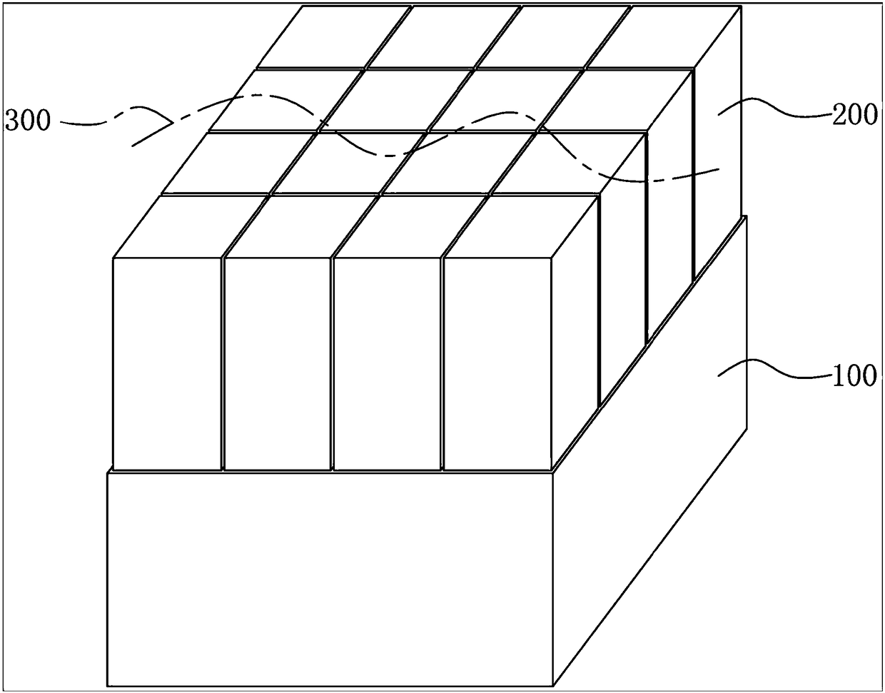
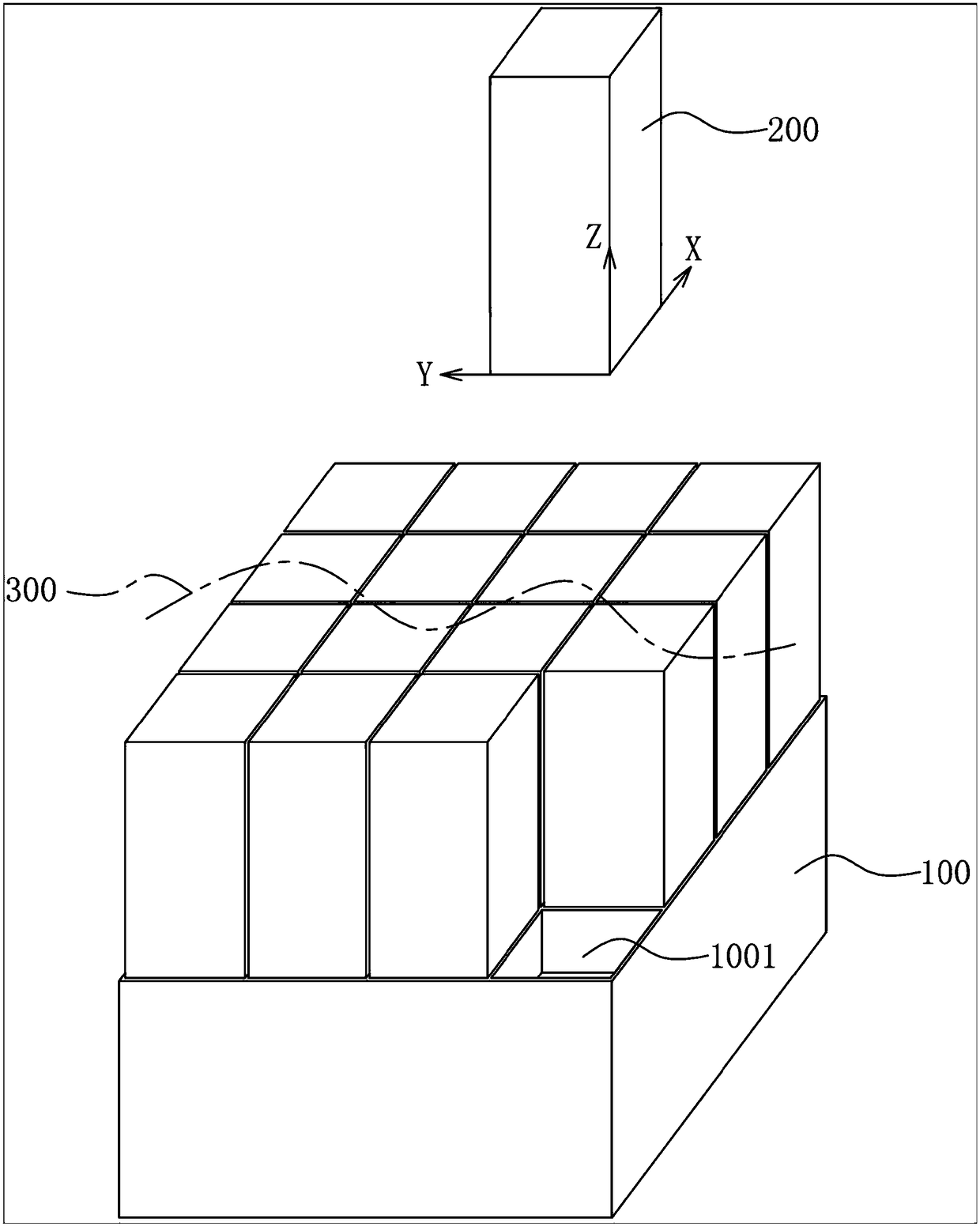
[0019] A mold exhaust mechanism of the present invention is applied in a mold. In this embodiment, the mold exhaust mechanism includes: an exhaust inlet base 100, and the exhaust inlet base 100 is provided with several Exhaust inlet sub-slot 1001, the exhaust inlet sub-slot 1001 is distributed in a grid shape; and a number of exhaust inlet sub-slots 200, the exhaust inlet sub-slot 200 is tightly fitted in the exhaust inlet sub-slot 1001 respectively, In this example, see figure 2 , the exhaust inlet 200 is partially placed in the exhaust inlet slot 1001, and the exhaust inlet 200 is a columnar body.

[0020] In this embodiment, the exhaust inlets 200 are respectively extended and arranged in the exhaust inlet sub slots 1001 in the transverse direction or the longitudinal direction.

[0021] In this embodiment, the distance between two adjace...


PUM

PropertyMeasurementUnit
Lengthaaaaaaaaaa
Widthaaaaaaaaaa

Abstract

Provided is a mold exhaust mechanism. The mold exhaust mechanism is applied to molds and includes an air exhaust insert base and multiple air exhaust inserts; the air exhaust insert base is provided with a plurality of air exhaust insert slots, and the air exhaust insert slots are distributed in a grid-like manner; and the air exhaust inserts are separately arranged in the air exhaust insert slotsin a close-fitting mode, and the air exhaust inserts are cylindrical bodies. According to the mold exhaust mechanism provided with the air exhaust inserts distributed in a grid-like manner, and moreover, a certain gap is formed between two adjacent air exhaust inserts, so that air in a mold cavity is discharged through air exhaust gaps when the product is molded. The exhaust mechanism simplifiesthe processing process, simplifies the assembly process and shortens the processing time.

Description

technical field [0001] The invention relates to a mold exhaust mechanism, in particular to a mold exhaust mechanism. Background technique [0002] There are often joint lines on plastic products. The joint line is a thin line formed by the molten material path or the confluence part above the molten material path. Not only two glue-in points will produce a joint line, but sometimes even one glue-in point will be caused by the product. The difference in structure produces a bonding line, and the direction of the bonding line is related to the position, size and flow temperature of the plastic injection point. However, in the plastic mold manufacturing industry, the requirements for appearance are particularly strict. There are many products that require the appearance surface to be high-mirror, and there must be no joint line. Design the exhaust inlet. The exhaust inlet currently used is made of flakes. This kind of flake exhaust inlet has the following disadvantages: [00...

Claims


Application Information

Patent Timeline
IPC IPC(8): B29C33/10
CPCB29C33/10
Inventor 杨怡
Owner 新昌县七星街道同亨模具厂
Why Eureka
Eureka Blog
Learn More