Protective film bonding device and method

A bonding device and protective film technology, applied in packaging and other directions, can solve the problems of indentation on the product surface, expensive equipment, piercing of OLED or TFE film layers, etc., to avoid the generation of air bubbles, indentation and folding Injury, reduce the effect of the probability of air bubbles

Active Publication Date: 2018-05-29
WUHAN CHINA STAR OPTOELECTRONICS SEMICON DISPLAY TECH CO LTD
View PDF6 Cites 9 Cited by
  • Summary
  • Abstract
  • Description
  • Claims
  • Application Information

AI Technical Summary

Problems solved by technology

[0003] At present, most panel manufacturers' OLED touch (organic light-emitting display touch) technology is still immature, so they will outsource the touch process, that is, make the touch panel and protective film into TP film (touch panel film). For similar products, The existing method of using roller film sticking will easily form indentations on the product surface, and if the factory environmental control is not good, resulting in more particles (particles) on the product surface, the risk of OLED or TFE film layer being pierced will be greatly increased. Increase
In addition, the existing technology needs to purchase additional defoaming equipment, and the equipment cost is relatively expensive
Furthermore, the existing technology cannot be fully compatible with strip-shaped protective films and sheet-shaped protective films, that is, the same equipment cannot meet the attachment requirements of strip stickers and surface stickers at the same time.

Method used


Image

  • Protective film bonding device and method
  • Protective film bonding device and method
  • Protective film bonding device and method

Examples


Embodiment Construction

[0029] In order to make the object, technical solution and advantages of the present invention more clear, the present invention will be further described in detail below in conjunction with the accompanying drawings and embodiments. It should be understood that the specific embodiments described here are only used to explain the present invention, not to limit the present invention.

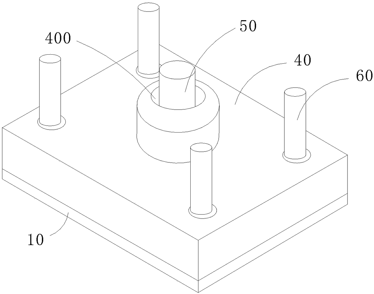
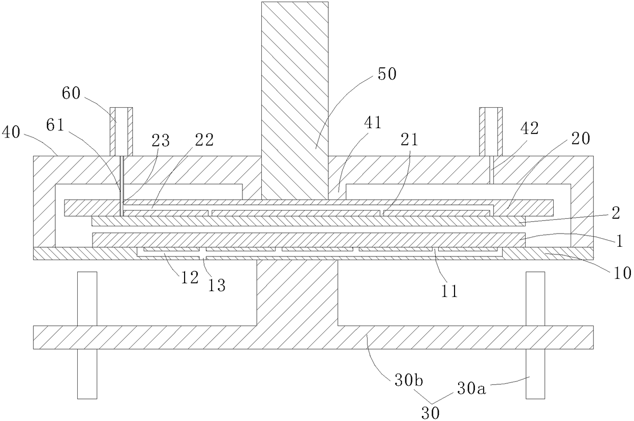
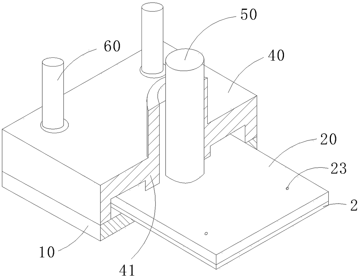
[0030] refer to figure 1 and figure 2 , the protective film bonding device of the embodiment of the present invention includes a stage 10, a pressure plate 20, a lifting mechanism 30 and an upper shell 40, the stage 10 is used to place the substrate 1 to be filmed, the pressure plate 20 is arranged opposite to the stage 10, and The pressing plate 20 is arranged above the stage 10, and includes a plurality of first grooves 21 for air to pass through, a first channel 22 communicating with all the first grooves 21, and a first air inlet 23 on the surface facing the stage 10. An air inlet 23 and ...


PUM


Abstract

The invention discloses a protective film bonding device. The protective film bonding device comprises a bearing platform, a pressing plate and first vacuum generating devices, wherein the bearing platform is used for placing a base plate to be bonded a film; the pressing plate is arranged in the opposite direction with the bearing platform and is arranged above the bearing platform, and the pressing plate comprises a plurality of first slots allowing air passing through arranged on the surface, facing the bearing platform, of the pressing plate, a first passage communicating with all the first slots and first air inlet holes, and the first air inlet holes and the first slots are on different surfaces of the pressing plate; and the first vacuum generating devices communicate with the firstair inlet holes and are used for generating vacuum suction force to adsorb the protective film on the surface of the pressing plate, and the bearing platform and the pressing plate can be close to each other to bond the protective film on the surface of the base plate. The invention further discloses a protective film bonding method. By means of the protective film bonding device and method, thegeneration probability of bubbles in the bonding process is reduced, the accurate bonding of the protective film is realized, pressure and break marks generated in the process of film bonding are alsoavoided, the situation that a product film layer is punctured by particles is also avoided, and the bonding requirements of strip-shaped and sheet-shaped protective films can be well met at the sametime.

Description

technical field [0001] The invention relates to the technical field of film bonding, in particular to a protective film bonding device and bonding method. Background technique [0002] The protective film lamination process (Top laminator) is generally after the TFE (Thin Film Encapsulation, thin film encapsulation) process or the Touch process (touch panel process). The purpose of the process is to attach a layer of PET (Polyethylene terephthalate, poly The protective film made of ethylene terephthalate) prevents the product from being damaged in the subsequent process and causing the product to be scrapped. [0003] At present, most panel manufacturers' OLED touch (organic light-emitting display touch) technology is still immature, so they will outsource the touch process, that is, make the touch panel and protective film into TP film (touch panel film). For similar products, The existing method of using roller film sticking will easily form indentations on the product su...

Claims


Application Information

Patent Timeline
Patent Type & Authority Applications(China)
IPC IPC(8): B65B33/02
Inventor 王璟
Owner WUHAN CHINA STAR OPTOELECTRONICS SEMICON DISPLAY TECH CO LTD
Why Eureka
Try Eureka