Wafer susceptor

A wafer carrying and wafer technology, which is applied in coating, gaseous chemical plating, metal material coating process, etc. Effect

Active Publication Date: 2018-05-29
GLOBALWAFERS CO LTD
View PDF4 Cites 8 Cited by
  • Summary
  • Abstract
  • Description
  • Claims
  • Application Information

AI Technical Summary

Problems solved by technology

[0006] The present invention provides a wafer carrying plate, which can solve the phenomenon that the inner edge of the wafer is easily drifted away caused by the centrifugal force during rotation, not only makes the wafer evenly heated but also can effectively realize uniform film formation

Method used


Image

  • Wafer susceptor
  • Wafer susceptor
  • Wafer susceptor

Examples


Embodiment Construction

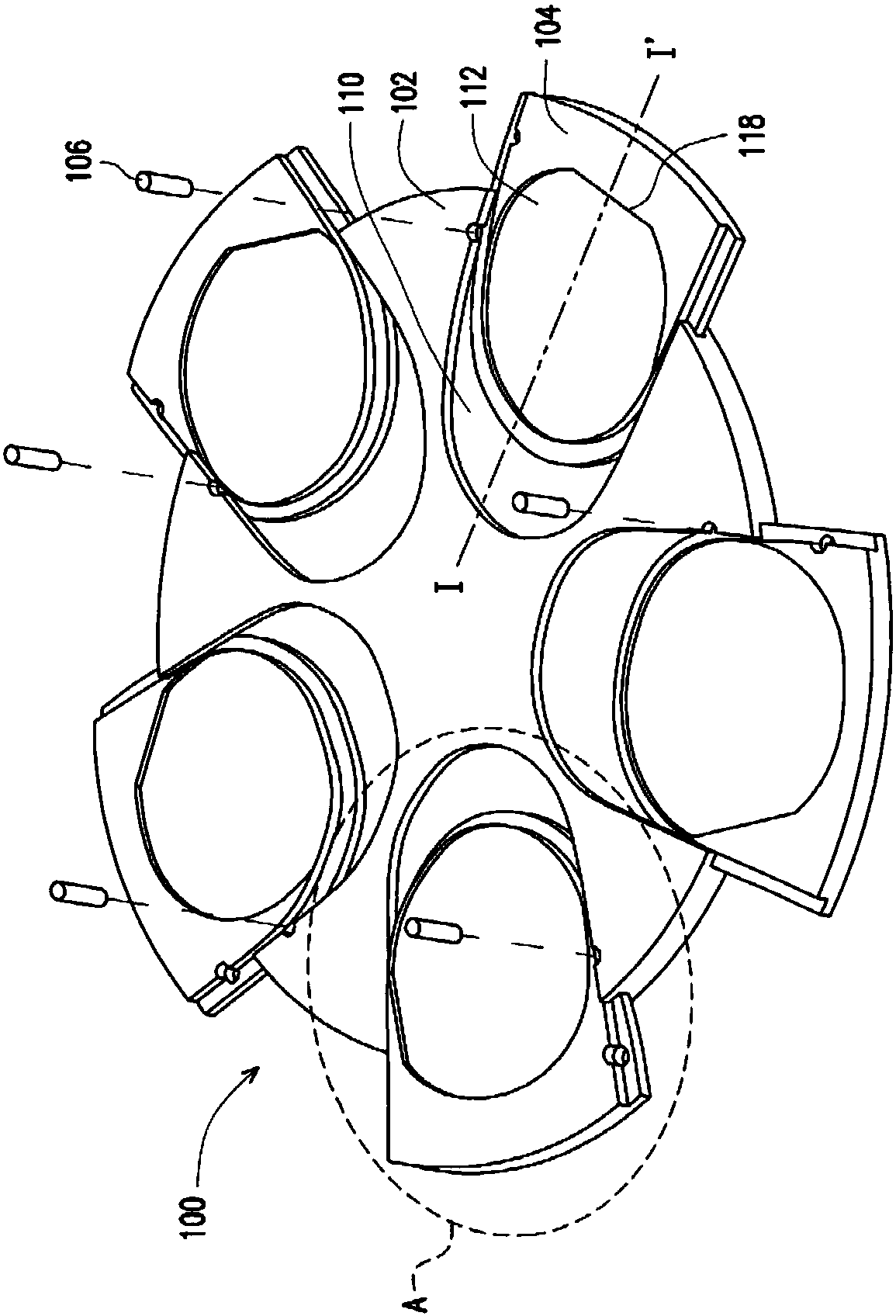
[0060] Figure 1A is a schematic diagram of a wafer carrier according to an embodiment of the present invention.

[0061] Please see first Figure 1A , the wafer susceptor 100 of the present invention includes a master plate 102 , several daughter plates 104 and several pins 106 . The wafer susceptor 100 can rotate clockwise or counterclockwise based on its center.

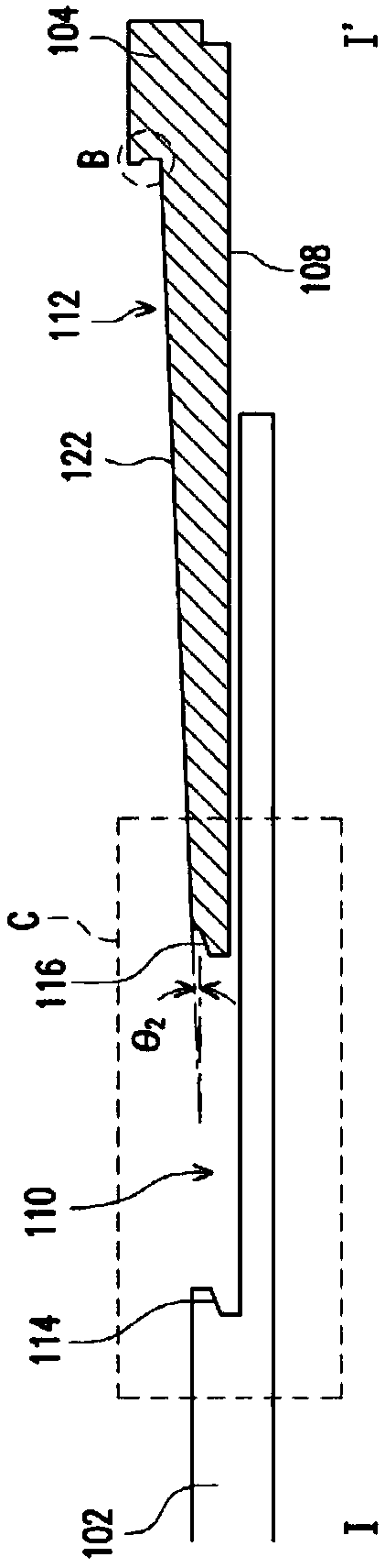
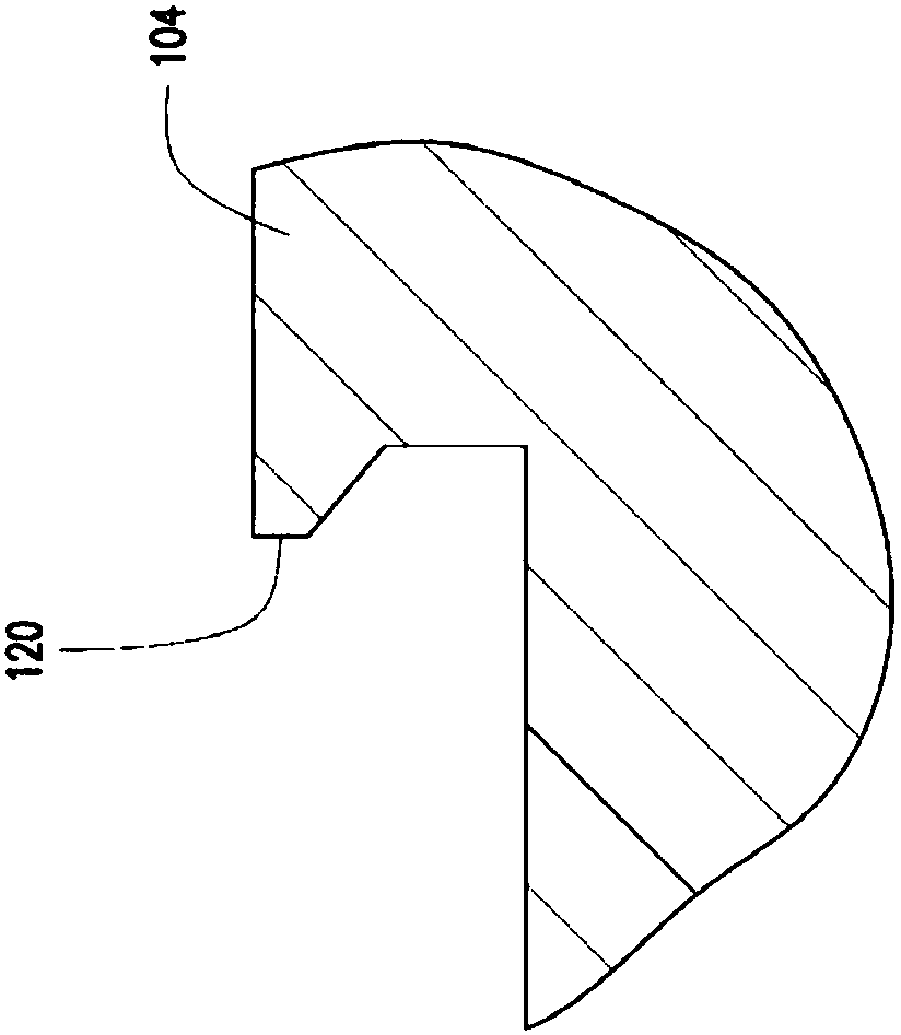
[0062] Figure 1B yes Figure 1A Sectional view along the line segment I-I'. Figure 1C yes Figure 1B Magnified view of region B of . Figure 1D yes Figure 1B Magnified view of region C. Figure 1E yes Figure 1A The enlarged view of the combination of the sub-disc and the master disc on which the wafer is placed in the area A of .

[0063]Please see Figure 1A and Figure 1B . The master disc 102 has a plurality of first grooves 110 . Several sub-discs 104 are respectively arranged in the first groove 110, and each sub-disc 104 has a second groove 112 for carrying wafers and a fitting slope 116 fitted ...


PUM

PropertyMeasurementUnit
angleaaaaaaaaaa
angleaaaaaaaaaa

Abstract

The invention provides a wafer susceptor which includes a main plate, minor plates, and plugs. The main plate has first notches. The minor plates are disposed in the first notches, respectively. Eachof the minor plates has a second notch for carrying a wafer and an engaging surface of inclination engages with a side surface of the first notch. A first angle of 20-45 degrees is provided between the engaging surface and a horizontal plane. The second notch has a flat side corresponding to a flat of the wafer. The flat side has an eave portion. The plugs are disposed between the main and minor plates to fix the minor plate, respectively. The wafer susceptor can solve the problem of drafting of inner edges of a wafer due to centrifugal force during rotation, so that the wafer is heated uniformly and a film can form uniformly effectively.

Description

technical field [0001] The present invention relates to a susceptor, in particular to a wafer susceptor. Background technique [0002] Generally speaking, in the chemical vapor deposition (Chemical Vapor Deposition, CVD) apparatus used in the epitaxial growth of the semiconductor manufacturing process, it is equipped with a heat source and a rotating mechanism under the wafer, and can supply a uniform process gas from above. Back heating method. [0003] In order to uniformly form a film on the wafer, the epitaxial reaction is generally performed under high-speed rotation. However, during rotation, the inner edge of the wafer tends to float away due to the centrifugal force, which makes the wafer unable to maintain a stable state, so that the effect of uniform film formation cannot be effectively achieved. [0004] Moreover, in the current technology, the wafer is directly placed in the groove on the wafer carrier plate, and there is still room for improvement in terms of ...

Claims


Application Information

Patent Timeline
Patent Type & Authority Applications(China)
IPC IPC(8): C23C16/458H01L21/687
CPCC23C16/4581H01L21/68785H01L21/68764H01L21/68771H01L21/687H01L21/67309
Inventor 林塘棋范俊一林嫚萱徐文庆
Owner GLOBALWAFERS CO LTD
Why Eureka
Try Eureka