Positioning device for phase shifter welding and method for positioning phase shifter by using positioning device

Pending Publication Date: 2021-01-01
COMBA RF TECH GUANGZHOU LTD +1
View PDF0 Cites 3 Cited by
  • Summary
  • Abstract
  • Description
  • Claims
  • Application Information

AI Technical Summary

Problems solved by technology

[0003] However, manual positioning will result in a poor positioning effect between the phase shifter and the power distribution board, resulting in a gap between the bottom surface of the cavity wall of the phase shifter and the welding pad of the power distribution board, which will affect the welding quality at the solder joint

Method used


Image

  • Positioning device for phase shifter welding and method for positioning phase shifter by using positioning device
  • Positioning device for phase shifter welding and method for positioning phase shifter by using positioning device
  • Positioning device for phase shifter welding and method for positioning phase shifter by using positioning device

Examples


Embodiment 1

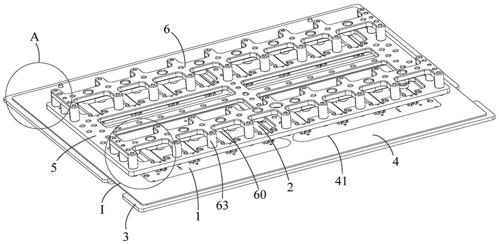
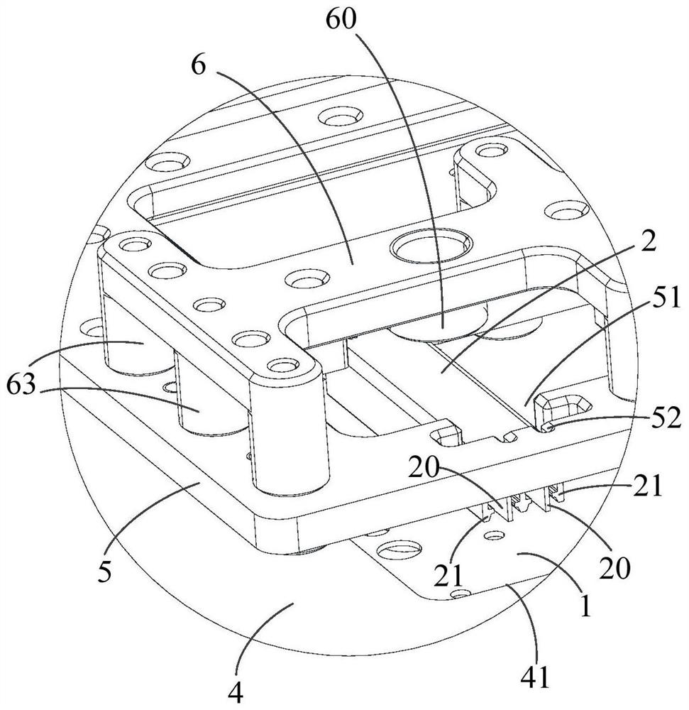
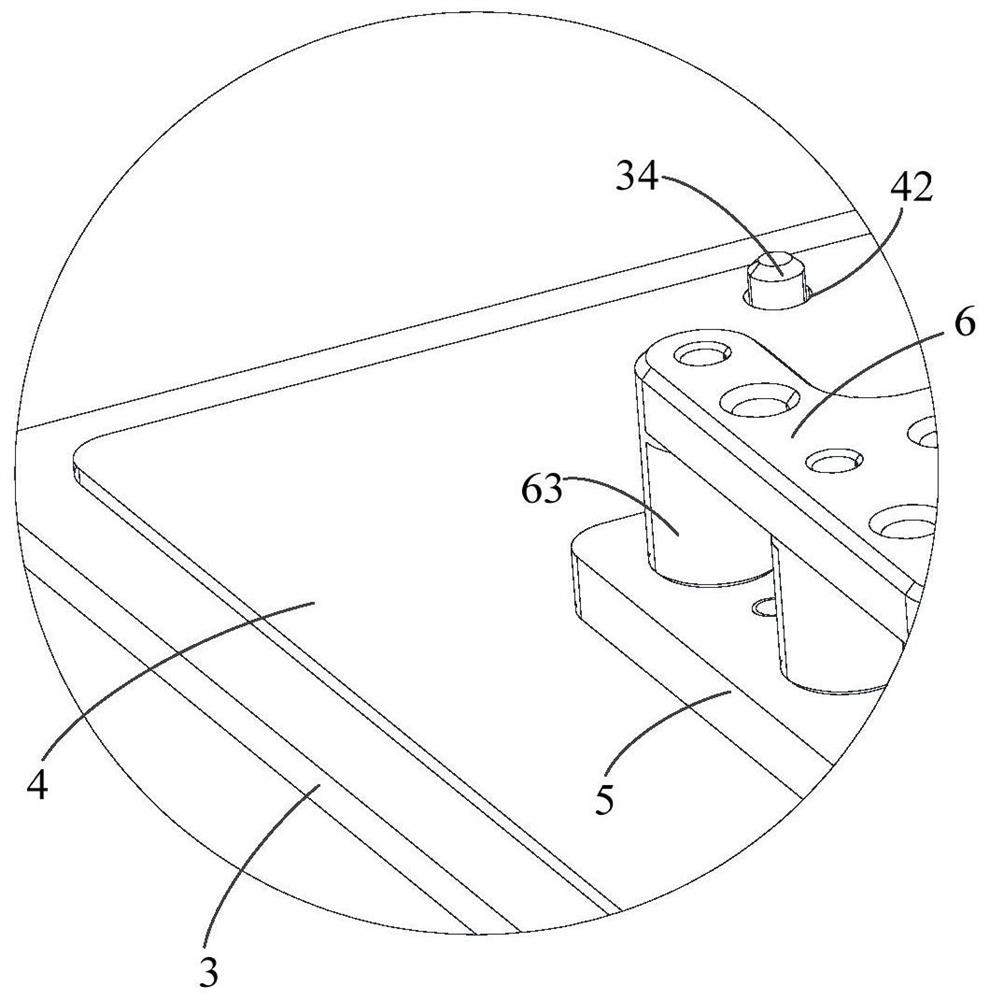
[0056] Phase shifters are the core components of base station antennas. When in use, the phase shifter and the power splitter board need to be soldered together by reflow soldering. Wherein, the side of the power splitter facing the phase shifter has a first pad, specifically, the bottom surface of the cavity wall of the phase shifter is welded and fixed to the first pad, that is, the phase shifter and the power splitter are welded vertically. Before welding, the phase shifter and power splitter need to be positioned, and then welded. If the positioning effect is poor, there will be a gap between the bottom surface of the cavity wall of the phase shifter and the first pad, resulting in weak solder joints and affecting the soldering quality.

[0057] Based on this, this embodiment provides a positioning device for phase shifter welding, which can ensure that the phase shifter sticks to the power sub-board and ensure the welding quality at the solder joints.

[0058] refer to ...

Embodiment 2

[0099] refer to Figure 16 As shown, the embodiment of the present disclosure also provides a method for positioning the phase shifter by using the positioning device for phase shifter welding, and the method can be executed by part or all of the positioning device for phase shifter welding in the above-mentioned embodiments.

[0100]combine Figure 1 to Figure 16 As shown, the positioning method is described below through specific embodiments, and the method specifically includes:

[0101] S101 , place the power distribution board 1 on the power distribution board positioning base 3 , and make the first positioning column 31 on the power distribution board positioning base 3 penetrate into the first positioning hole 12 of the power distribution board 1 .

[0102] S102 , installing the phase shifter limiting plate 5 on the positioning bottom plate 3 of the power dividing plate.

[0103] Specifically, the second positioning column 53 can be set on the phase shifter limiting p...


PUM


Abstract

The invention relates to a positioning device for phase shifter welding and a method for positioning a phase shifter by using the positioning device. The positioning device comprises a power dividingplate positioning bottom plate and a phase shifter limiting plate which are oppositely arranged. A limiting hole used for limiting the phase shifter is formed in the phase shifter limiting plate; thephase shifter is located in the limiting hole; the surface, facing the phase shifter limiting plate, of the power dividing plate positioning bottom plate forms a bearing surface used for bearing a power dividing plate; and a first positioning column used for being connected with a first positioning hole in the power dividing plate in a matched mode is arranged on the power dividing plate positioning bottom plate. The positioning device for phase shifter welding further comprises a pressing structure arranged on the phase shifter limiting plate, wherein the pressing structure is used for pressing the phase shifter on the power dividing plate, so that the bottom face of the cavity wall of the phase shifter can be attached to a first bonding pad on the face, facing the phase shifter, of the power dividing plate, a positioning effect on the phase shifter is improved, and gaps generated by contact between the phase shifter and the power dividing plate can be effectively eliminated.

Description

technical field [0001] The present disclosure relates to the technical field of phase shifter welding, in particular to a positioning device for phase shifter welding and a method for positioning the phase shifter. Background technique [0002] Phase shifters are the core components of base station antennas. In specific use, it is necessary to weld and fix the bottom surface of the cavity wall of the phase shifter and the pad of the power distribution board. Before welding, it is necessary to position the phase shifter and the power distribution board. Position on the power splitter board, then solder. [0003] However, manual positioning will lead to poor positioning effect between the phase shifter and the power distribution board, resulting in gaps between the bottom surface of the cavity wall of the phase shifter and the welding pad of the power distribution board, which will affect the welding quality at the solder joints. Contents of the invention [0004] In order...

Claims


Application Information

Patent Timeline
Patent Type & Authority Applications(China)
IPC IPC(8): B23K37/04
CPCB23K37/04B23K37/0443
Inventor 龚奎马红智
Owner COMBA RF TECH GUANGZHOU LTD
Why Eureka
Try Eureka