Three-dimensional code nut ring latch

A three-dimensional code screw and three-dimensional code technology, applied in the field of locks, can solve the problems of low material strength of the lock cylinder, low key rate, and difficult processing of the key slot, etc., to achieve a firm locking method, reduce processing difficulty, and simplify the basic structure. Effect

Inactive Publication Date: 2018-05-29
武思军
View PDF0 Cites 0 Cited by
  • Summary
  • Abstract
  • Description
  • Claims
  • Application Information

AI Technical Summary

Problems solved by technology

[0002] At present, mechanical locks are mainly pin locks and blade locks with key slots. Because the processing of key slots is difficult, the material of the lock cylinder can only use low-strength brass. The existing pin lock cylinder uses an axial lock cylinder. This requires that there must be a key slot and a key handle rod. The pins are arranged in a one-dimensional linear arrangement, and the key teeth are also arranged in a one-dimensional linear arrangement. The concave and convex angle of the key teeth must be less than about 45 degrees to facilitate insertion into the lock cylinder, making the longest pin The length of the difference between the shortest pin and the pin cannot be much larger than the diameter of the pin, which greatly limits the number of pins and the number of pins on the one-dimensional line, usually only single digits, and the code bits are generally arranged according to the one-dimensional line. The number of keys is only a few thousand, the key rate is low, and the strength of the lock core material is small, so that various methods of breaking the lock emerge in endlessly. Generally, the lock tongue of the lock is directly inserted. Therefore, most thieves destructively unlock the lock by prying open the door. The locking tongue, which shows that the common way of inserting the locking tongue is very fragile

Method used


Image

  • Three-dimensional code nut ring latch
  • Three-dimensional code nut ring latch
  • Three-dimensional code nut ring latch

Examples


Embodiment Construction

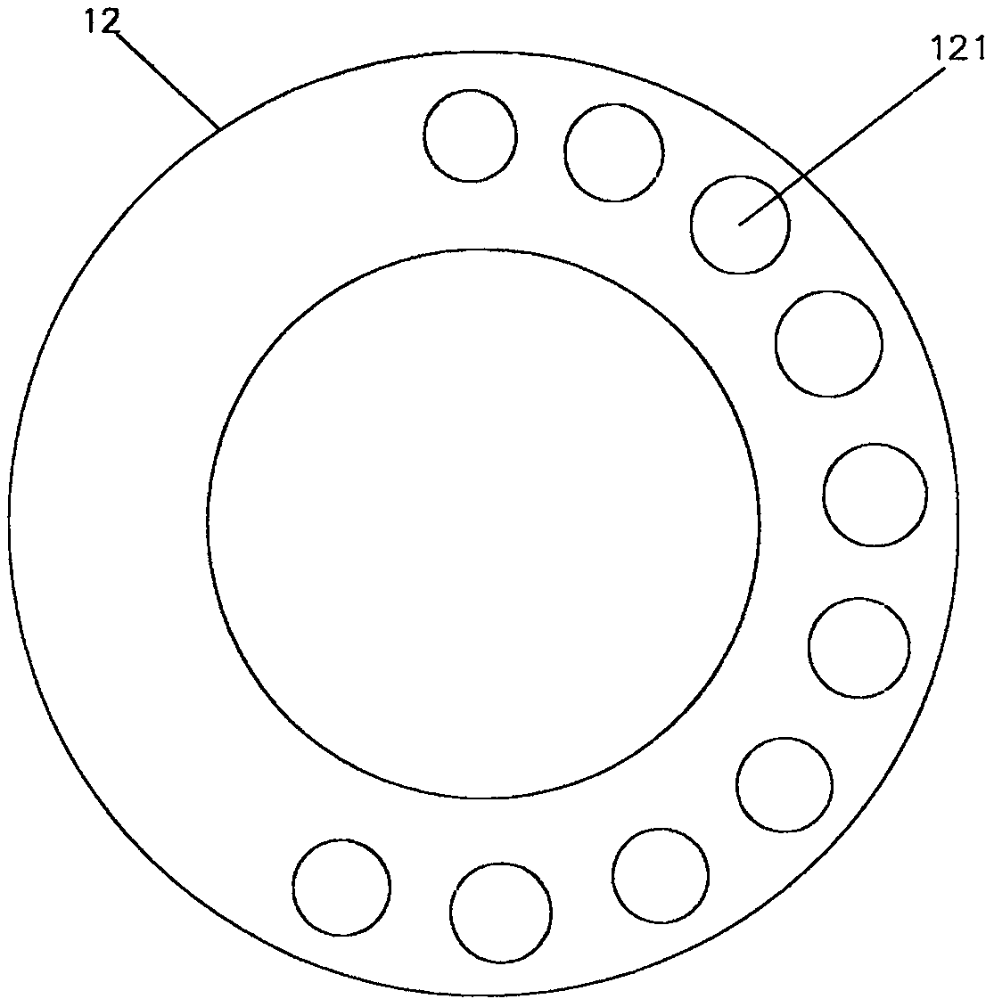
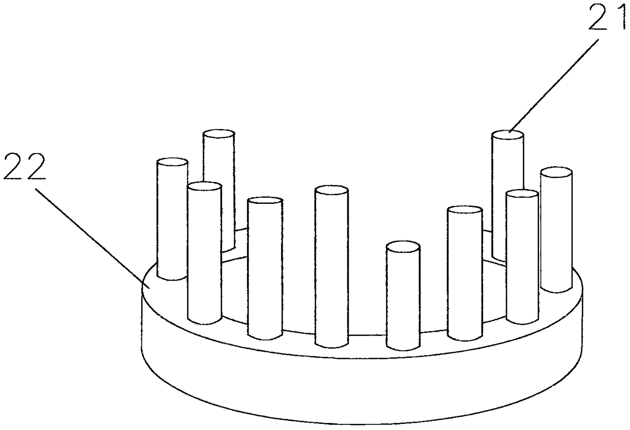
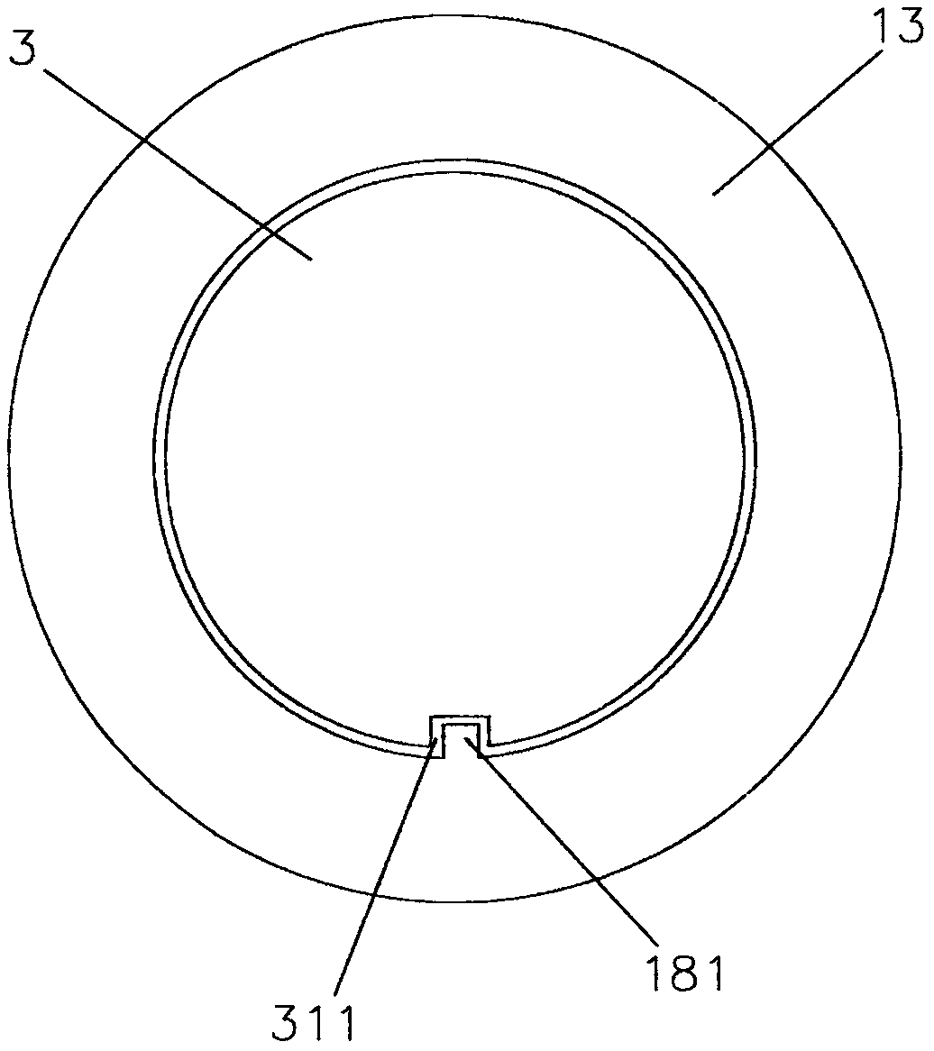
[0024] Implementation column 1, such as figure 1 , figure 2 , image 3 , Figure 4 and Figure 5 Shown: a LU-shaped three-dimensional code nut padlock, including a three-dimensional code nut lock cylinder 1, and a lock beam 3, the three-dimensional code nut lock cylinder 1, including a lock code screen 12, a plug honeycomb 13, and a lock case 17, lock code 11, embolus 14 and spring 15. In the lock case 17, the rear end face of the code lock screen 12 is in close contact with the front face of the embolus honeycomb 13, and the code lock screen 12 is arranged in a two-dimensional manner, with many holes 121 that are thin at the front and thick at the back, and the two ends pass through. , the front is thinner and the rear is thicker in order to prevent the lock code 11 from coming out of the lock code screen 12. These holes 121 are equipped with various code numbers of lock codes 11 to form a three-dimensional layout of the lock code 11. The lock code 11 is in the shape of ...


PUM


Abstract

The invention discloses a three-dimensional code nut ring latch, and relates to a lock which overcomes the defects of the low key strength of an existing mechanical lock and the small material strength of the lock core. The three-dimensional code nut ring latch gives up a traditional shaft type key cylinder, in three dimensions of a space, a lock code and a key code are fully distributed, and thekey core is directly used for pushing a lock core needle rod to reach more than one trillion high key quantity and high strength lock core. The lock core technology adopted is that a lock core screenattaches tightly with an embolus honeycomb, the lock core is provided with holes in an arrangement mode of two dimensions; the holes are internally provided with multiple lock cores with a variety ofcore numbers to form a three dimensional layout of the lock cores; the embolus honeycomb is provided with multiple nests in an arrangement mode of the two dimensions; the nests are internally providedwith embolus and springs; the center of the embolus honeycomb is provided with a threaded hole; the center of the lock core screen is provided with an axial hole; one end of a lock beam is provided with an axial part, and the other end of the lock beam is provided with a screw end; the axial hole is matched with the axial part; and the screw hole is meshed with the screw end.

Description

technical field [0001] The invention relates to a lock, in particular to a lock core with a three-dimensional spatial layout and a nut padlock capable of spiral precession. Background technique [0002] At present, mechanical locks are mainly pin locks and blade locks with key slots. Because the processing of key slots is difficult, the material of the lock cylinder can only use low-strength brass. The existing pin lock cylinder uses an axial lock cylinder. This requires that there must be a key slot and a key handle rod. The pin codes are arranged in a one-dimensional linear arrangement, and the key teeth are also arranged in a one-dimensional linear arrangement. The concave and convex angle of the key teeth must be less than about 45 degrees to facilitate insertion into the lock cylinder, making the longest pin The length of the difference from the shortest marble cannot be much larger than the diameter of the marble, which greatly limits the number of marbles and the numb...

Claims


Application Information

Patent Timeline
Patent Type & Authority Applications(China)
IPC IPC(8): E05B67/22E05B67/28E05B35/00E05B19/00
CPCE05B67/22E05B35/00E05B67/28
Inventor 武思军
Owner 武思军
Why Eureka
Try Eureka