Pump body component and compressor with it

A technology of components and pump bodies, applied in the field of compressors, can solve the problems of detachment of the inner wall of the sliding vane cylinder and the reduction of the working performance of the pump body components.

Pending Publication Date: 2018-05-29
GREE ELECTRIC APPLIANCES INC
View PDF4 Cites 13 Cited by
  • Summary
  • Abstract
  • Description
  • Claims
  • Application Information

AI Technical Summary

Problems solved by technology

[0004] The main purpose of the present invention is to provide a pump body assembly and a compressor with it, so as to solve the problem in the prior art that the head of the slide plate of the pump body assembly is easily separated from the inner wall of the cylinder, resulting in a decrease in the working performance of the pump body assembly question

Method used


Image

  • Pump body component and compressor with it
  • Pump body component and compressor with it
  • Pump body component and compressor with it

Examples


Embodiment 1

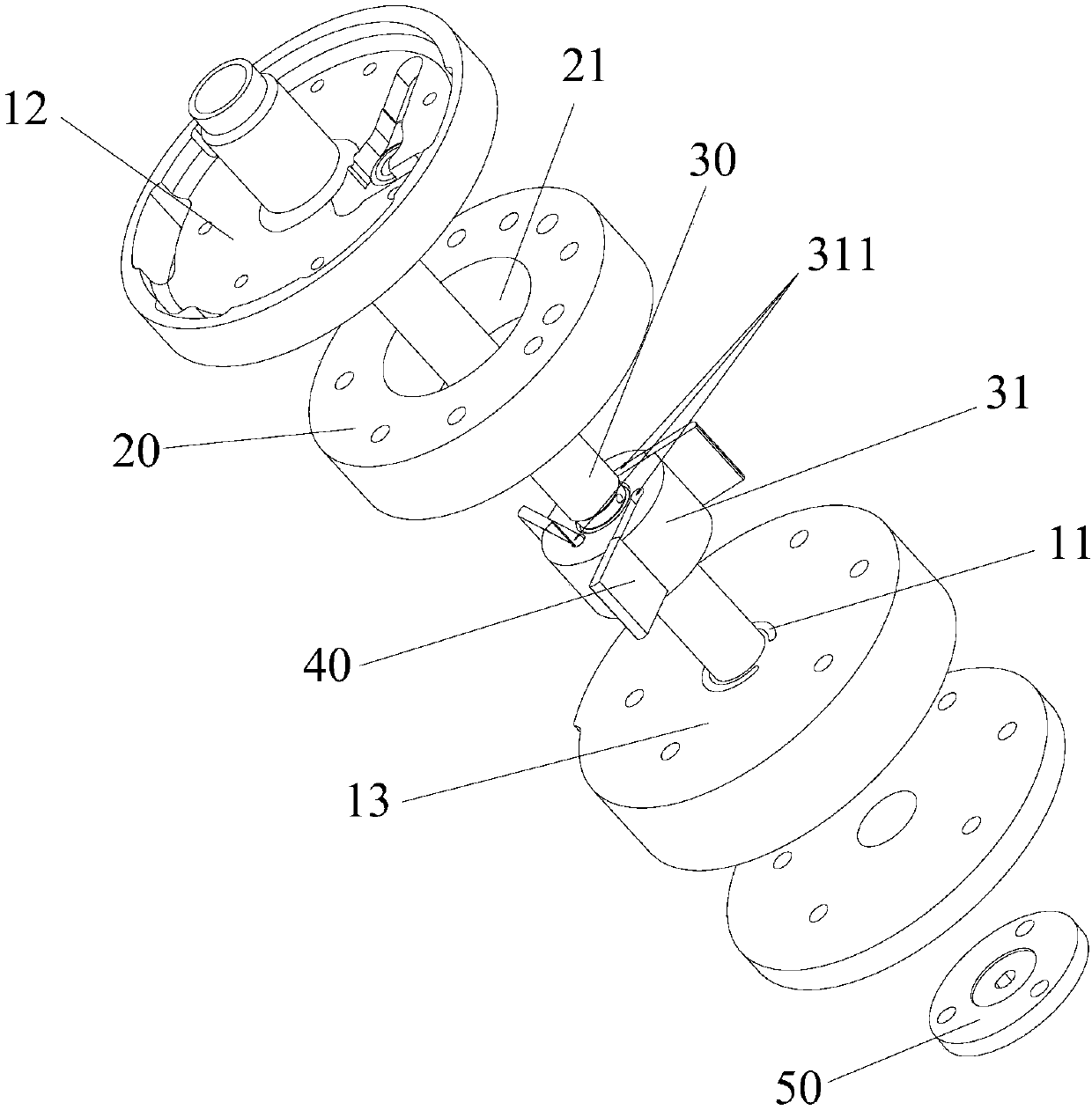
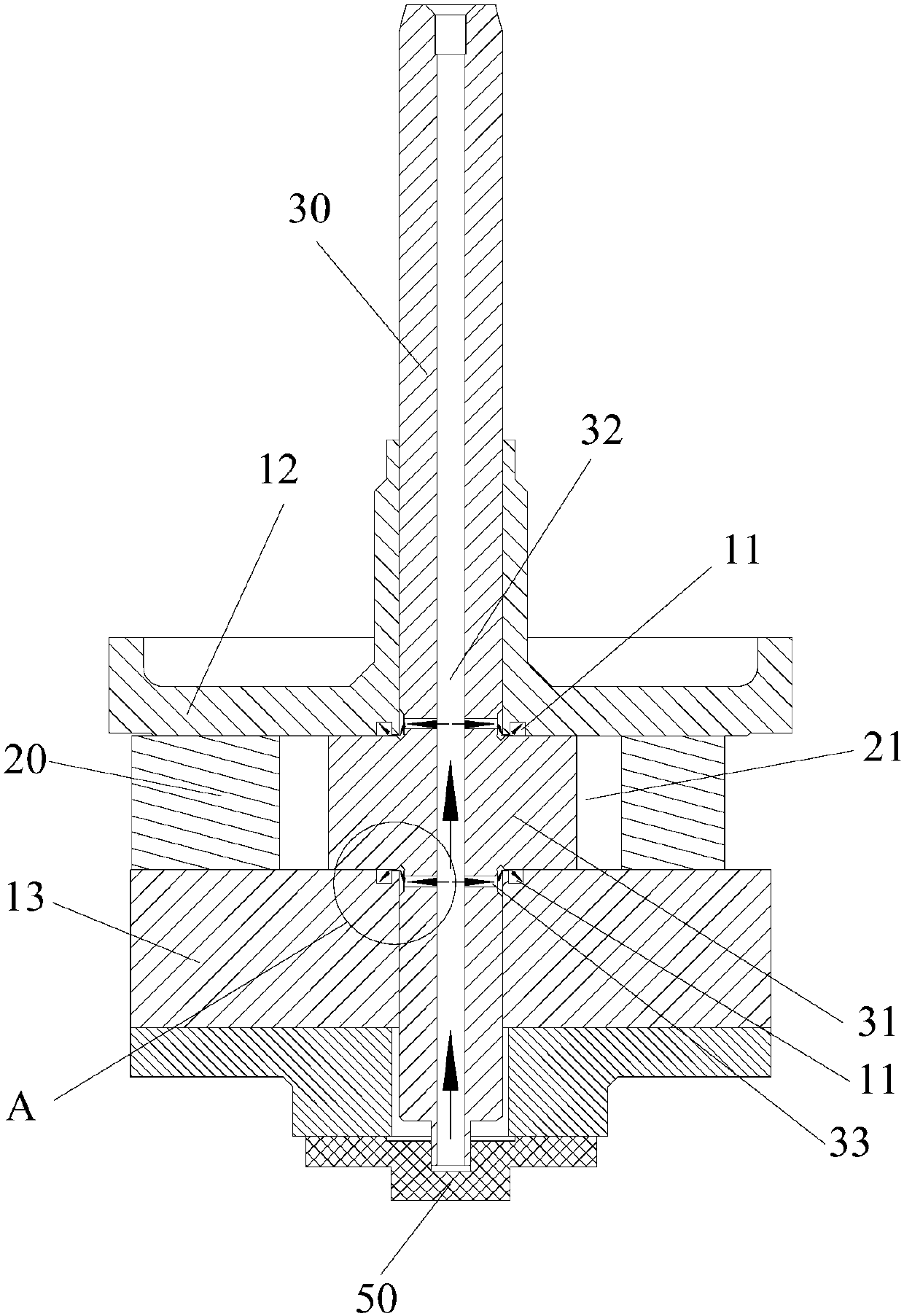
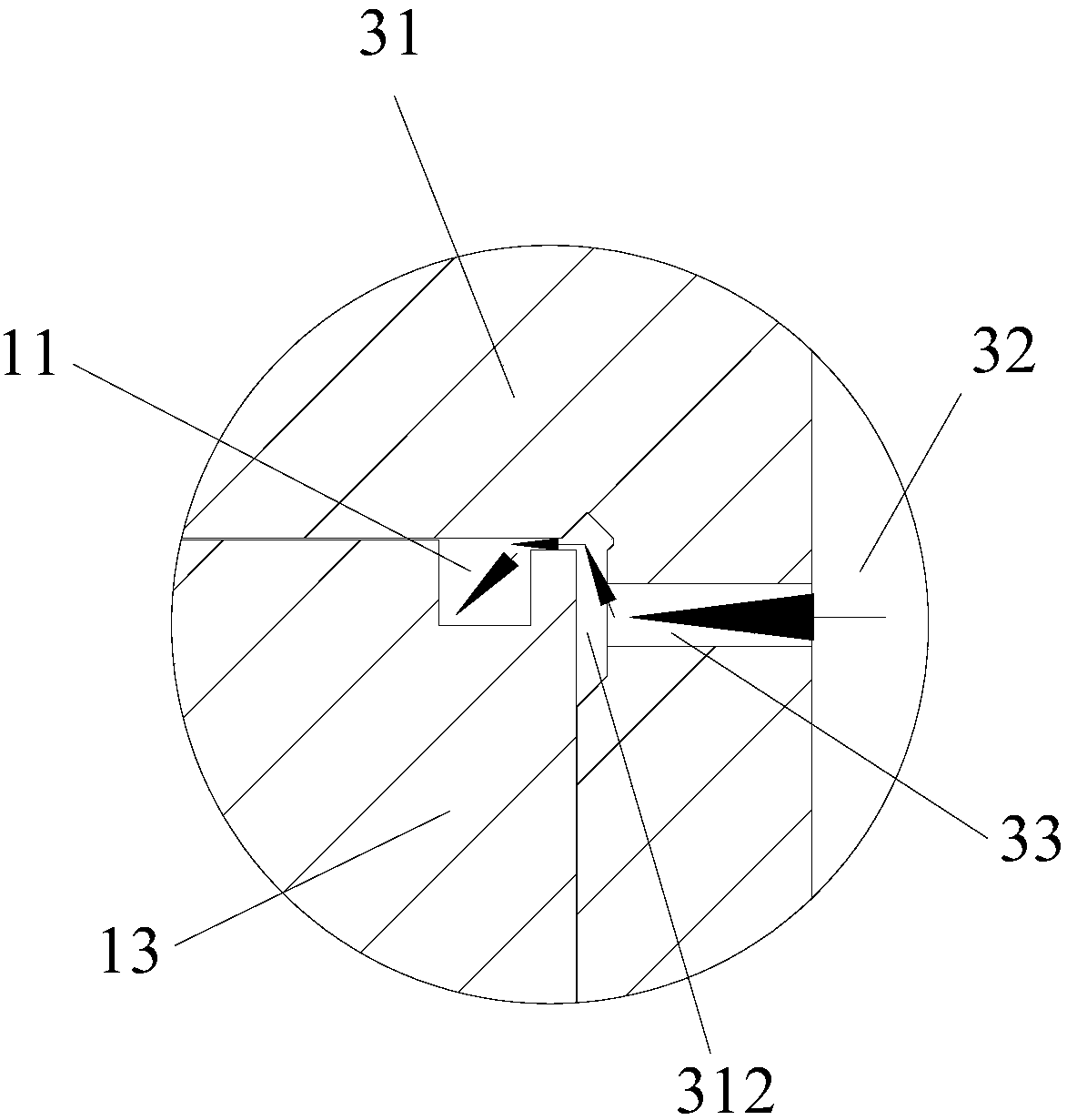
[0051] Such as Figure 1 to Figure 6 As shown, the pump body assembly includes a structural member, a cylinder 20 , a rotating shaft 30 and a plurality of sliding vanes 40 . Among them, there are two structural parts, at least one structural part has a back pressure oil structure, the back pressure oil structure is a back pressure arc groove 11, and the arc number φ1 of the back pressure arc groove 11 is greater than or equal to 220°. The cylinder 20 is arranged between the two structural members. The rotating shaft 30 passes through the two structural components and the cylinder 20 , and the rotor portion 31 of the rotating shaft 30 has a plurality of slide slots 311 . A plurality of sliding vanes 40 are slidably arranged in a plurality of sliding vane grooves 311, part or all of the back pressure arc grooves 11 communicate with the sliding vane grooves 311, and lubricating medium can enter into the back pressure arc grooves 11 to adjust the sliding vane grooves The pressur...

Embodiment 2

[0071] The difference between the pump body assembly of the second embodiment and the first embodiment is that the structure of the back pressure arc groove 11 is different.

[0072] Such as Figure 12 to Figure 14 As shown, the back pressure arc grooves 11 are connected end to end to form an annular groove. In this way, the lubricating medium can enter into the annular groove, circulate in the annular groove and take away the heat in the cylinder 20, thereby reducing the temperature inside the cylinder 20, cooling and cooling the cylinder 20, and improving the working efficiency of the pump body components. performance. At the same time, the above-mentioned structure is simple in structure, easy to process and realize, and further reduces the processing cost of the pump body assembly.

[0073] Such as Figure 12 to Figure 14As shown, the annular groove includes a first arc groove section 111 and a second arc groove section 112 that communicate with each other, and the sum ...


PUM


Abstract

The invention provides a pump body component and compressor with it, wherein the pump body component comprises structure pieces, an air cylinder, a rotary shaft, and multiple slide pieces; there are two structure pieces of which one is provided with a back pressure oil structure, the back pressure oil structure is a back pressure arc slot, and the gradient of the back pressure arc slot is more than or equal to 220 degrees; the air cylinder is arranged between two structure pieces, the rotary shaft crosses through two structure pieces and the air cylinder, and a rotor part of the rotary shaft is provided with multiple slide piece slots; multiple slide pieces are glidingly and correspondingly arranged in multiple slide piece slots, a part of or all of the back pressure arc slots are connected with slide piece slots; the lubricating medium can enter the back pressure arc slots so as to adjust the pressure in the tail parts of the slide piece slots and guarantee that the head parts of theslide pieces are always contacted with the inner wall of the air cylinder. The pump body component and the compressor can effectively solve the problem of reduced working performance of the pump bodycomponent for the head part of the slide piece of the pump body component in the prior art is easy to isolate from the inner wall of the air cylinder.

Description

technical field [0001] The invention relates to the technical field of compressors, in particular to a pump body assembly and a compressor having the same. Background technique [0002] During the operation of the pump body assembly, in order to ensure that the sliding vane can smoothly protrude from the sliding vane groove, a back pressure chamber is usually provided at the tail of the sliding vane (the sliding vane tail cavity formed by the sliding vane and the sliding vane groove and the upper, The back pressure groove of the lower flange), and the high pressure or medium pressure oil in the oil pool (through the flow channel to produce a throttling effect) is passed into the back pressure chamber to generate a force on the sliding vane, which is used to overcome the sliding vane The gas pressure in the front and rear chambers where the head of the slider is located and the friction force generated by the cylinder and the head of the slide, etc., prevent the head of the s...

Claims


Application Information

Patent Timeline
Patent Type & Authority Applications(China)
IPC IPC(8): F04C18/344F04C29/00F04C29/02
CPCF04C18/3441F04C29/0021F04C29/023
Inventor 胡余生万鹏凯徐嘉任丽萍罗发游吴飞史正良张荣婷文智明
Owner GREE ELECTRIC APPLIANCES INC
Why Eureka
Try Eureka