Oil supply device

A technology of oil supply device and oil tank, which is applied in the direction of bearing components, engine components, engine lubrication, etc., can solve the problems of lubricating oil waste and intermittent oil supply, etc., achieve a firm structure, prevent continuous oil dripping, and ensure uniformity Effect

Active Publication Date: 2018-05-29
泾县凡泽科技服务有限公司
View PDF6 Cites 6 Cited by
  • Summary
  • Abstract
  • Description
  • Claims
  • Application Information

AI Technical Summary

Problems solved by technology

However, the existing oil supply device cannot supply oil intermittently, which is easy to cause waste of lubricating oil

Method used


Image

  • Oil supply device

Examples


Embodiment Construction

[0014] The following is further described in detail through specific implementation methods:

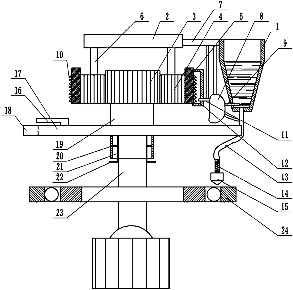
[0015] The reference signs in the drawings of the description include: fuel tank 1, fixed plate 2, main gear 3, external gear 4, internal gear 5, rotating shaft 6, connecting plate 7, air bag 8, oil control plate 9, locking teeth 10, ejector rod 11 , rotating block 12, hose 13, telescopic tube 14, oil cup 15, squeeze plate 16, squeeze plate 17, oil drain groove 18, clamping shaft 19, spring 20, clamping plate 21, button 22, drive shaft 23 , Bearing 24.

[0016] The embodiment is basically as attached figure 1 Shown: an oil supply device, including a fuel tank 1 and a clamping mechanism, the fuel tank 1 is filled with lubricating oil, the clamping mechanism includes a clamping shaft 19, the bottom of the clamping shaft 19 is provided with a clamping groove, and the clamping groove is provided with There are two clamping plates 21, a spring 20 is connected between the groove wall of ...


PUM


Abstract

The invention relates to the field of automobile performance testing, in particular to an oil supply device. The oil supply device includes an oil tank and further includes a clamping mechanism. The clamping mechanism is fixedly connected to an extruding plate. The extruding plate is provided with an extruding plate and an oil draining groove. The extruding plate is located above the oil draininggroove. The clamping mechanism is fixedly connected with a main gear. The outer side of the main gear is provided with an inner gear in a sleeved mode. An outer gear meshes with the position between the main gear and the inner gear simultaneously. The outer side of the outer gear is provided with a fixing plate. A rotating shaft is connected with the position between the fixing plate and the outergear. One end of the rotating shaft is fixedly connected to the fixing plate. The other end of the rotating shaft is rotatably connected with the outer gear. The outer wall of the inner gear is rotatably connected with a rotating block. The rotating block is connected with an ejector rod in a sliding mode. The oil tank is connected with a hose. The hose communicates with an oil cup. The junctionof the oil tank and the hose is connected with an oil control plate. A gasbag is arranged between the oil tank and the extruding plate. A gas pipe communicates with the position between the gasbag andthe hose. The gasbag is fixedly connected with the oil control plate and the ejector rod. Intermittent oil supply is achieved through the scheme of the oil supply device.

Description

technical field [0001] The invention relates to the field of automobile performance detection, in particular to an oil supply device. Background technique [0002] There are many types of vehicle performance testing, including vehicle safety testing, vehicle power testing, vehicle reliability testing, vehicle economy testing, and vehicle noise and exhaust emission status testing. The inspection of automobile performance includes not only the inspection of the entire body and system of the automobile, but also the partial inspection of the parts of the automobile. The detection of automobile parts is usually carried out on the detection device. Generally, the detection device must rotate at high speed. For example, when testing the wear resistance of automobile tires, the parts in the detection device need to rotate at high speed, such as the bearing in the detection device. A large amount of heat is generated by the bearing under high-speed rotation. In the prior art, lubri...

Claims


Application Information

Patent Timeline
Patent Type & Authority Applications(China)
IPC IPC(8): F16N7/08F16C37/00
CPCF16C37/00F16N7/08
Inventor 卢加权
Owner 泾县凡泽科技服务有限公司
Why Eureka
Try Eureka