A thin-walled cylindrical centrifugal gas flowmeter

A gas flowmeter and thin-walled cylinder technology, applied in indirect mass flowmeters, mass flow measurement devices, etc., can solve problems such as low range ratio, short service life, non-linearity, etc., to overcome short service life and long service life , real-time response fast effect

Active Publication Date: 2020-04-10
马宁敏
View PDF4 Cites 0 Cited by
  • Summary
  • Abstract
  • Description
  • Claims
  • Application Information

AI Technical Summary

Problems solved by technology

[0010] The invention is a device for measuring gas flow by differential pressure method, which has simple structure, fast real-time response and high measurement accuracy, and overcomes the disadvantages of traditional plate-hole differential pressure method, such as low range ratio of gas flow measurement, non-linearity and difficult calibration, etc. At the same time, it also overcomes the shortcomings of the hot wire gas flow sensor, which is easily affected by water in the gas and has a short service life.

Method used


Image

  • A thin-walled cylindrical centrifugal gas flowmeter
  • A thin-walled cylindrical centrifugal gas flowmeter
  • A thin-walled cylindrical centrifugal gas flowmeter

Examples


Embodiment Construction

[0034] Embodiments of the present invention are described in detail below, the examples being shown in the drawings, wherein the same or similar reference numerals denote the same or similar elements or elements having the same or similar functions throughout. The embodiments described below by referring to the figures are exemplary and are intended to explain the present invention and should not be construed as limiting the present invention.

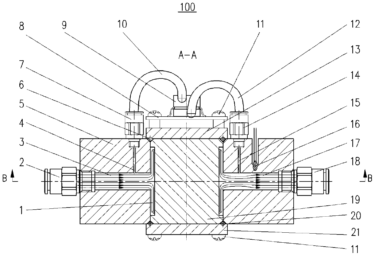
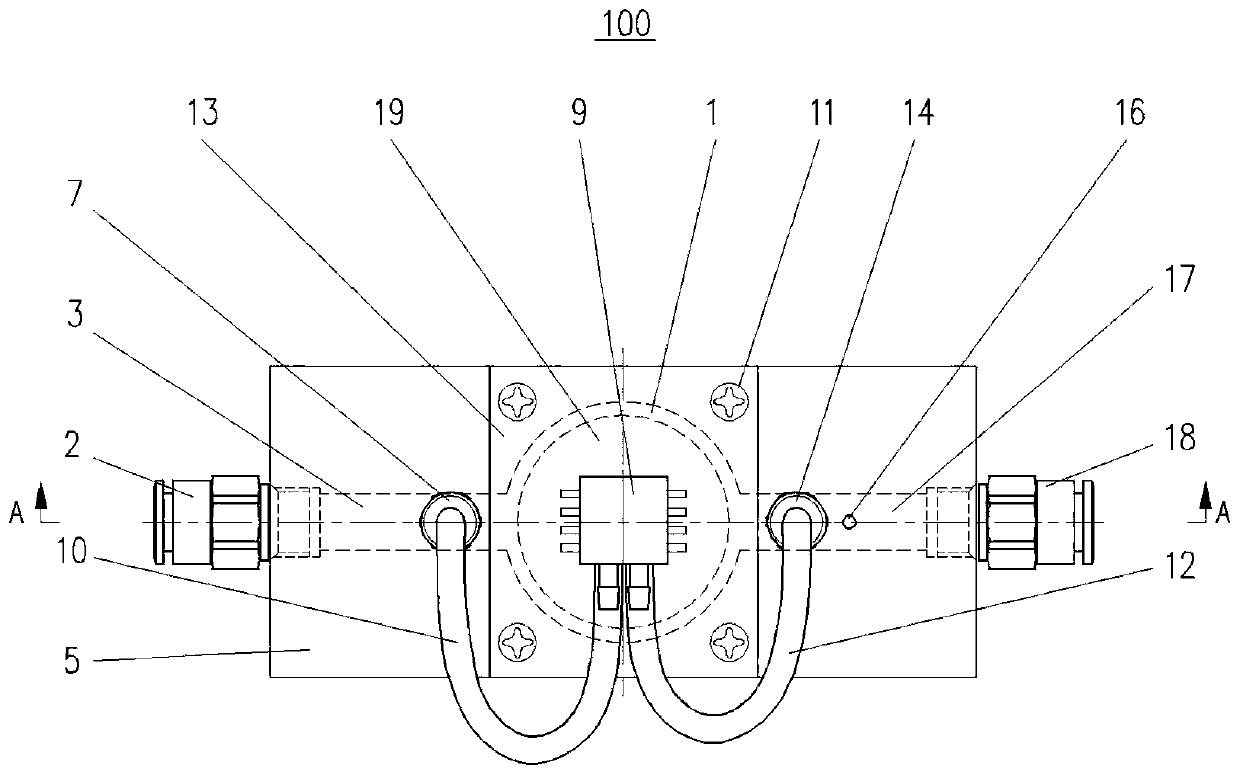
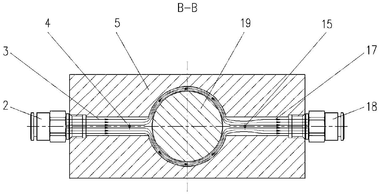
[0035] Refer below Figure 1 to Figure 8 A flow meter 100 according to an embodiment of the present invention is described.

[0036] In one embodiment of the present invention, the airway body 5, the cylinder 19, the upper sealing cover 13, the lower sealing cover 21, etc. can be made of metal or non-metal. In other applications, the above parts can also be processed or injection molded with plastics as required.

[0037] In one embodiment of the present invention, the main installation method is as follows: as figure 1 with 5As sh...


PUM


Abstract

The invention discloses a gas mass flow meter which comprises a flow meter body. A flow meter main body is arranged on the flow meter body and comprises a thin-walled cylindrical centrifugal type cavity (hereinafter referred to as cavity). The cavity comprises a gas duct body and a cylinder. The gas duct body is provided with a gas inlet, a front gas duct, a front pressure measuring point, a reargas duct, a rear pressure measuring point and a gas outlet. Centrifugal force is formed through the cylindrical cavity so that gas can make sufficient contact with the thin wall of the cavity, gas molecular kinetic energy is reduced, the pressure of gas flowing through the cavity is reduced, the variation of pressure before and after the gas flows through the cavity is measured through a differential pressure sensor, compensation is conducted through a temperature sensor, and the mass flow of the gas is calculated. The linear correspondence of the measured differential pressure value and the flow can be realized. The flow meter is high in repeatability, precision, durability and practicability and suitable for measuring various types of gases.

Description

technical field [0001] The invention relates to a gas flow meter, which can be applied to the fields of industrial instrument measurement and medical equipment, for example, it can measure the flow of various gases with high precision in medical ventilators and anesthesia machines. Background technique [0002] At present, a traditional plate orifice gas flowmeter is widely used in the market. The method of measuring the gas pressure difference at both ends of the throttling element in the air channel by a differential pressure sensor is used to measure the mass and flow rate of the gas. Flow meters have the following main disadvantages: [0003] (1) The gas flow range is relatively low; [0004] (2) Poor linearity of gas flow; [0005] (3) It is not easy to calibrate during use; [0006] Therefore, the traditional plate orifice differential pressure gas flowmeter is suitable for measurement occasions with large gas flow and low accuracy requirements. [0007] At present...

Claims


Application Information

Patent Timeline
Patent Type & Authority Patents(China)
IPC IPC(8): G01F1/88
CPCG01F1/88
Inventor 不公告发明人
Owner 马宁敏
Why Eureka
Try Eureka