Elastic vibration electric field instrument

An electric field meter and elastic vibration technology, which can be used in electrostatic field measurement and other directions to solve problems such as short service life.

Inactive Publication Date: 2003-09-17
NAT SPACE SCI CENT CAS
View PDF0 Cites 0 Cited by
  • Summary
  • Abstract
  • Description
  • Claims
  • Application Information

AI Technical Summary

Problems solved by technology

[0003] The purpose of the patent of the present invention is to design an elastic vibration electric field meter, which has the advantage of long life of continuous operation for more than several years, and overcomes the shortcoming of short service life in the prior art

Method used


Image

  • Elastic vibration electric field instrument
  • Elastic vibration electric field instrument
  • Elastic vibration electric field instrument

Examples


Embodiment 1

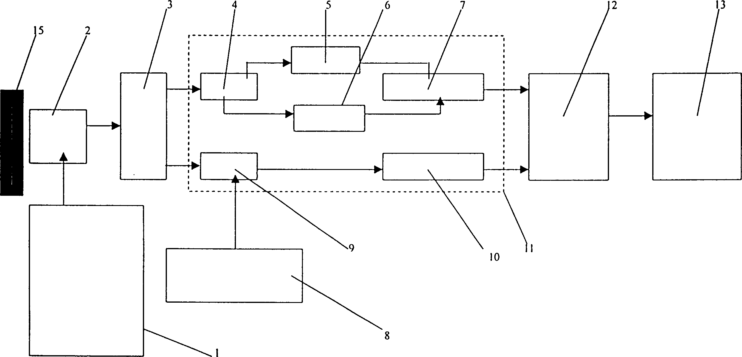
[0013] Embodiment 1: The elastic vibration type electric field instrument that produces resonance with shrapnel, its schematic diagram is shown in figure 2 .

[0014] figure 2 , when the detection panel 2 is at the position of the solid line in the figure, it is completely exposed to the external electric field. When it is at the dotted line position in the figure, it is completely within the shielding of the shell (metal plate) 15, and the shrapnel 1.4 drives the detection panel 2 to change its position, and periodically protrudes and retracts the shell (metal plate) 15; the detection panel 2 and shrapnel 1.4 are insulated and connected; in the external electric field, the current formed by the induced charge on the detection panel 2 is detected by the galvanometer 3 . Detection signal is sent in the software processor 11, at first carries out A / D conversion by A / D converter 4, then amplitude meter 5 and frequency meter 6 obtain amplitude value and frequency value, delive...

Embodiment 2

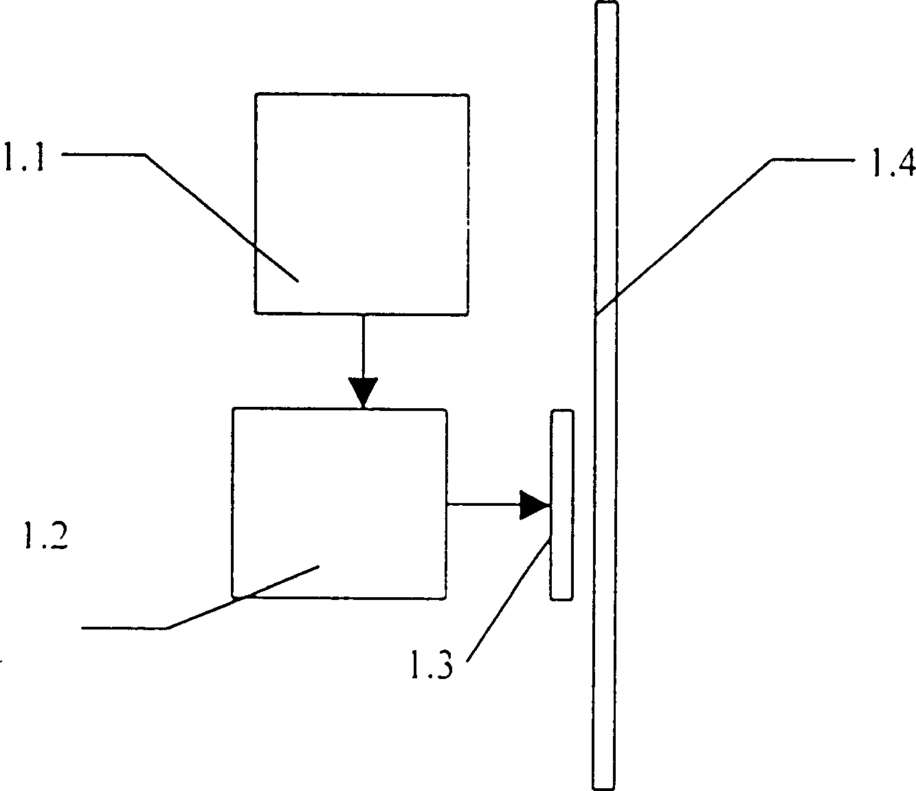
[0020] Embodiment two: the electric bell can be used to replace the vibrator. There are two kinds of electric bells, both of which can be used as the vibration driver in this program. One is direct current excitation, see diagram 2-1 . Among the figure, the spring sheet 1.4 is connected with a contact sheet 1.1. When in the state shown in the figure, because the contact screw 1.2 is connected with the contact piece 1.1, the circuit is connected, and the DC power supply makes the electromagnet 1.3 with a strong magnetic field, and the spring piece 1.4 is attracted. Cause the contact piece 1.1 and the contact screw 1.2 to leave, the current is interrupted, the magnet 1.3 loses its magnetism, the spring piece 1.4 returns to its original position with its inherent elastic force, and the contact piece 1.1 is connected with the contact screw 1.2, and the next cycle begins. Just go round and begin to make leaf spring 1.1 vibrate like this.

[0021] The advantage of this electric...

Embodiment 3

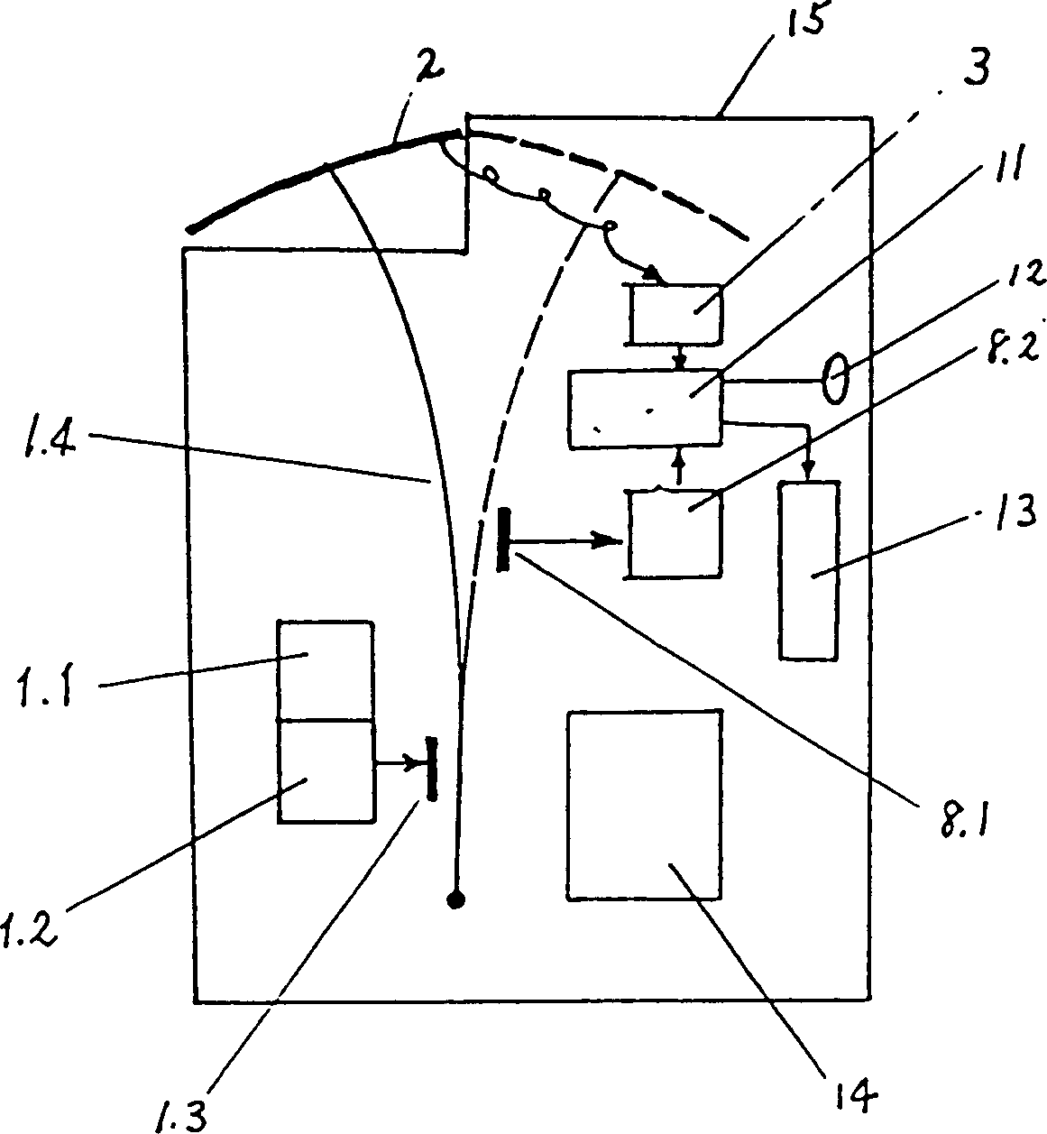
[0022] Embodiment three: another kind of electric bell is alternating current excitation, Figure 2-2 shown. In the figure, the AC driving coil 1.1 attracts and repels the magnetic sheet 1.2 alternately, and constitutes a resonant mechanism with the spring 1.3. Make the induction metal sheet fixed on the magnetic sheet 1.2, that is, the detection panel 2 protrude or retract into the grounding shell 15.


PUM


Abstract

The invention relates to the technical field of elastic-vibration measurement of atmospheric DC electric field strength. The elastic vibration electric field meter uses simple harmonic vibration to make the conductor detection panel protrude and retract the ground shielding panel. In the external electric field to be tested, the detection panel will induce alternating induction charges, which can be detected through the micro current detection circuit. The alternating current formed by the alternating induced charge can be used to obtain the magnitude of the external electric field, and the polarity of the electric field can be obtained by synchronous detection with the resonant waveform. Because the electric field meter has no rotating parts and no friction between hardware, it has a long service life.

Description

technical field [0001] The patent of the present invention relates to the technical field of atmospheric electric field strength measurement, in particular to the technical field of elastic vibration measurement of atmospheric electric field strength. Background technique [0002] It is the main principle of existing electric field meters at home and abroad to measure the atmospheric electric field strength by using the phenomenon that conductors can generate induced charges in the electric field. The most popular at present is the field mill electric field meter, or the rotating electric field meter. Usually, a piece of conductor that generates induced charge is alternately covered and exposed by another piece of grounded conductor, so that the intensity of induced charge changes with time to form a current. Then through the current amplification circuit for display and recording. Generally all use the way that motor rotates to make grounding conductor sheet alternately c...

Claims


Application Information

Patent Timeline
IPC IPC(8): G01R29/12
Inventor 庄洪春
Owner NAT SPACE SCI CENT CAS
Why Eureka
Try Eureka