Rapid radar detection method for unmanned aerial vehicle targets

A detection method and unmanned aerial vehicle technology, applied in radio wave measurement systems, radio wave reflection/re-radiation, measurement devices, etc., can solve problems such as large amount of calculation

Active Publication Date: 2018-05-29
成都电科智达科技有限公司
View PDF7 Cites 12 Cited by
  • Summary
  • Abstract
  • Description
  • Claims
  • Application Information

AI Technical Summary

Problems solved by technology

The existing third type of algorithm has a large amount of c

Method used

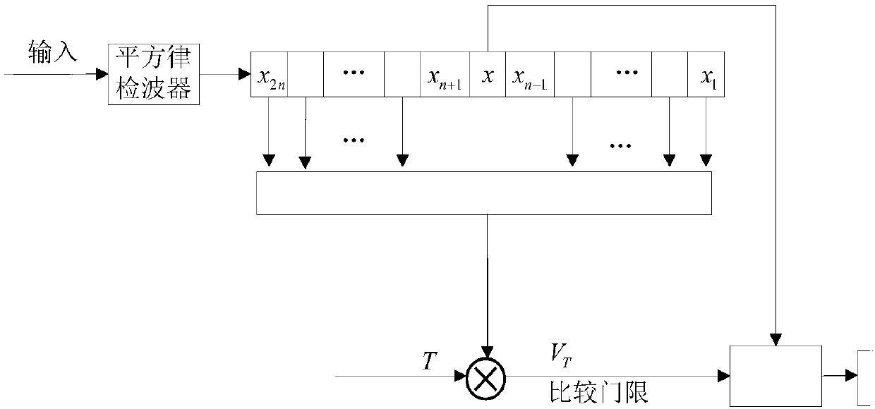
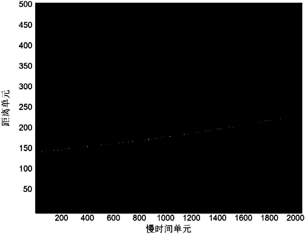

Image

  • Rapid radar detection method for unmanned aerial vehicle targets
  • Rapid radar detection method for unmanned aerial vehicle targets
  • Rapid radar detection method for unmanned aerial vehicle targets

Examples


Embodiment Construction

[0080] The technical solution of the present invention will be described in detail below in conjunction with the drawings:

[0081] The signal emitted by the radar in the present invention is a linear frequency modulation (LFM) signal, namely

[0082]

[0083] In the formula, rect(·) represents the rectangular function, T r Represents the pulse width, γ represents the frequency modulation slope, f 0 Indicates the carrier frequency. Make Here Express time, that is, distance time; t m =mT, m=0,1,2,... represents slow time, T represents pulse repetition time.

[0084] Assuming that there are K moving targets, the signal received by the radar is:

[0085]

[0086] In the formula, c=3×10 8 Represents the speed of light, A k,0 Represents the reflection coefficient of the kth target, r k (t m ) Represents the slant distance between the kth target and radar. Taking into account the jerk, r k (t m )It can be expressed as:

[0087]

[0088] Where, a k,0 Represents the initial distance from th...


PUM


Abstract

The invention belongs to the technical field of radar target detection, and specifically relates to a rapid detection and high-order motion parameter estimation method for radar maneuvering targets. According to the technical scheme, low, small and slow targets with complex motion are mainly detected through a radar, a method for solving distance movement and Doppler migration which occur when thetargets with the complex motion perform long-term coherent accumulation is provided, the parameter estimation performance is improved at the same time, the calculation amount is reduced, and therefore the purpose of rapidly detecting the targets is achieved.

Description

Technical field [0001] The present invention belongs to the technical field of radar target detection, and specifically relates to a rapid radar detection and method for UAV targets. Background technique [0002] With the maturity of drone technology and the sharp drop in the price of related products, various types of drones have been used in different fields. However, while drones have brought convenience to people, they have also become criminal tools in the hands of criminals. Due to the lack of human-machine supervision and control measures, the phenomenon of drone abuse and illegal flying has become increasingly serious. Faced with the threat of such targets, Radar has aroused widespread attention on UAV target detection methods. However, the echo signal of traditional surveillance radar is too weak, making it difficult to detect UAV targets. [0003] As we all know, long-term coherent accumulation can increase the signal-to-noise ratio and improve the radar's motion param...

Claims


Application Information

Patent Timeline
IPC IPC(8): G01S7/41G01S13/56G01S13/536
Inventor 曹宗杰
Owner 成都电科智达科技有限公司
Why Eureka
Try Eureka