
High-current DC contactor

A DC contactor and high current technology, applied in the direction of relays, electromagnetic relays, detailed information of electromagnetic relays, etc., can solve the problems of increasing the contactor opening distance and increasing the volume of the contactor, so as to improve the current level, save space and ensure effective Effect of insulation distance

Active Publication Date: 2018-05-29
BEIJING CED RAILWAY ELECTRIC TECH
View PDF3 Cites 1 Cited by
  • Summary
  • Abstract
  • Description
  • Claims
  • Application Information

AI Technical Summary

Problems solved by technology

[0003] At present, most DC contactors in the domestic market use snap-in electromagnets. Since the output force value of snap-in electromagnets will drop sharply as the stroke increases, with the development needs of the rail transit industry, DC contactors with higher breaking capacity will be required. The increase of the breaking capacity will lead to the increase of the opening distance of the contactor, which requires the electromagnet to provide a larger stroke. In the limited space of the locomotive, it is impossible to increase the volume of the contactor infinitely, which requires the entire power and transmission of the contactor. system optimization

Method used


Image

  • High-current DC contactor
  • High-current DC contactor
  • High-current DC contactor

Examples


Embodiment 1

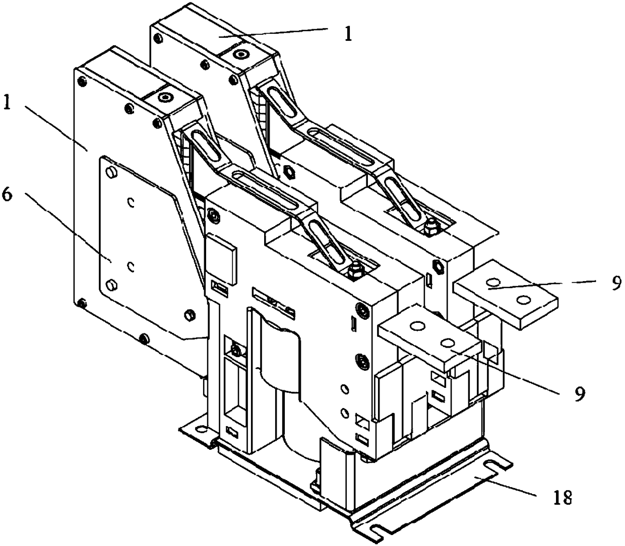
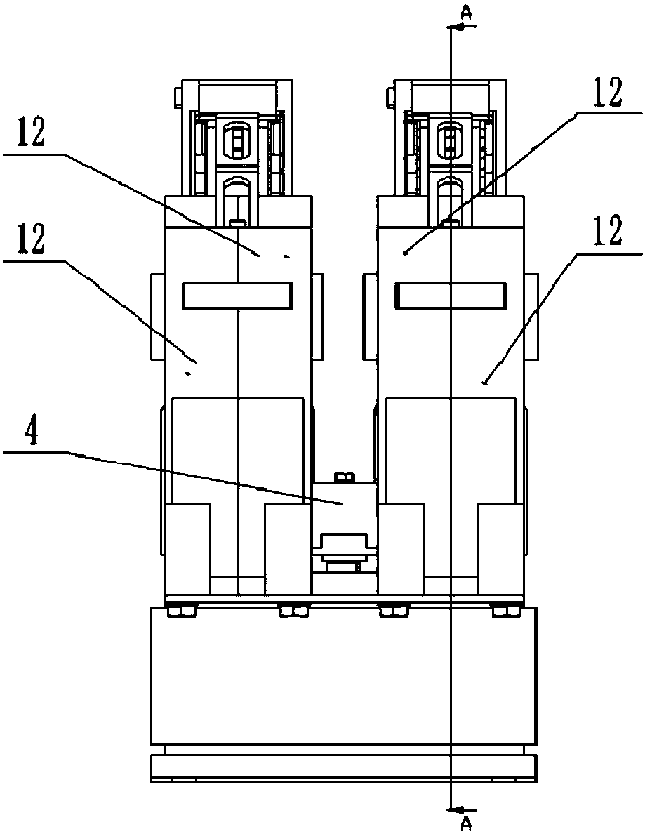
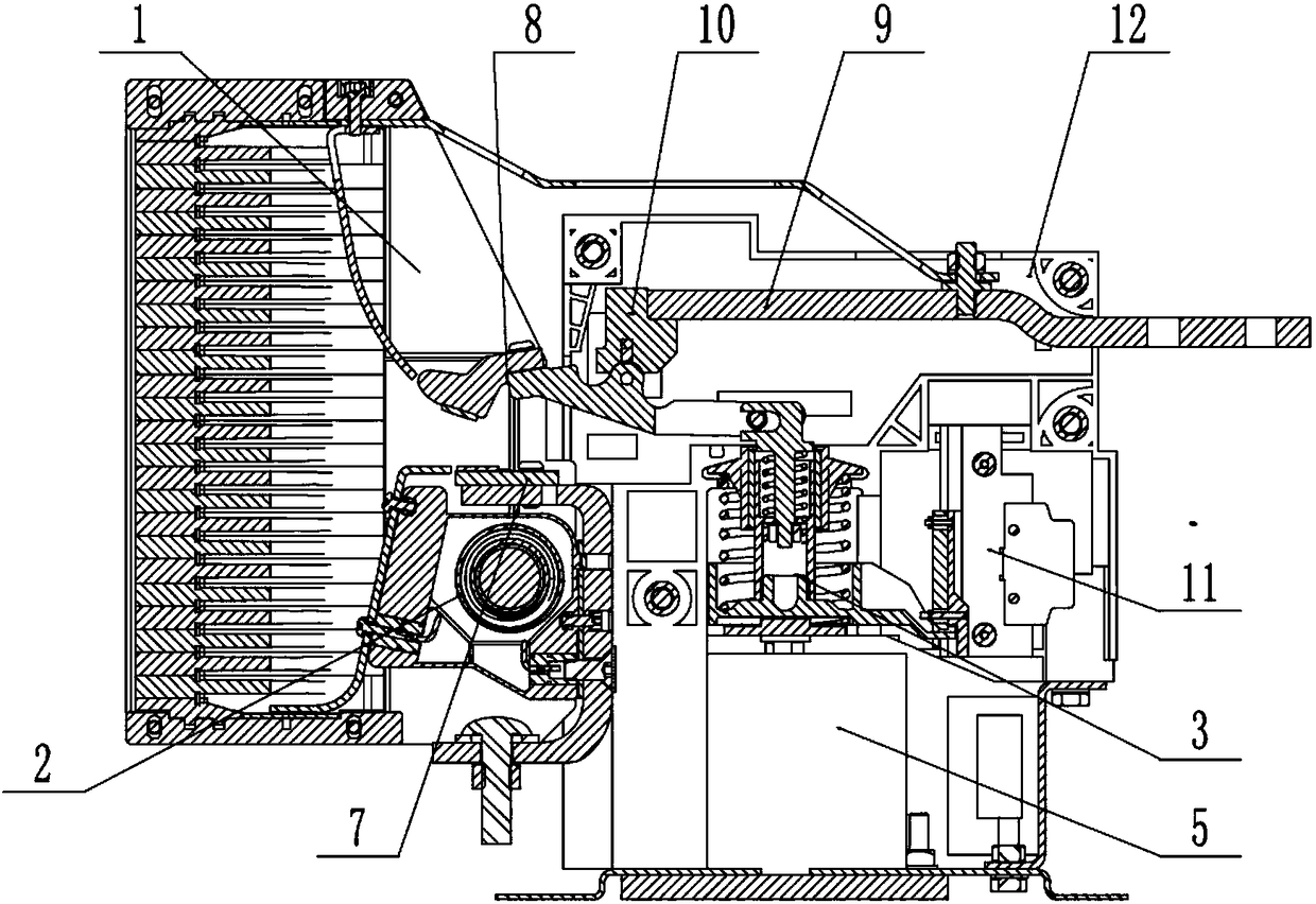
[0036] like Figures 1 to 10 As shown, a high-current DC contactor includes two sets of DC contact bodies and a set of electromagnetic drive mechanism. The DC contact body includes an arc extinguishing chamber 1, a magnetic blowing system 2, a spring system 3, a magnetic guide plate 6, Static contact 7, moving contact 8, conductive copper bar 9, support seat 10, micro switch assembly 11 and contactor housing 12; the electromagnetic drive mechanism includes a guide drive block 4, an electromagnet 5 and a base 18; Among them, the arc extinguishing chamber 1 and the magnetic blowing system 2 constitute the arc extinguishing system. The arc extinguishing chamber 1 here includes a plurality of clay grids, and the multi-clay grids and the contactor shell 12 constitute the arc extinguishing chamber 1. The magnetic blowing system 2 adopts a magnetic Blowing coil structure; the spring system 3 and the guide drive block 4 constitute the dynamic system, the electromagnet 5 and the magnet...


PUM


Abstract

The invention discloses a high-current DC contactor comprising two sets of DC contact bodies and a set of electromagnetic driving mechanism. A DC contact mechanism includes an arc extinguishing chamber (1), a magnetic blowing system (2), a spring system (3), a magnetic conducting plate (6), a static contact (7), a moving contact (8), a conductive copper row (9), a support base (10), a micro switchassembly (11), and a contactor shell (12). The electromagnetic drive mechanism includes a guide driving block (4), an electromagnet (5) and a base (18). A form of a snap-type electromagnet which is often used in existing products on the market is changed, a suction-type electromagnet is used as a power element, with a redesigned driving system, the space is saved as much as possible in the same breaking capacity, the requirements of a railway locomotive for dimensions are satisfied, the effective insulation distance of a contactor is ensured, and the current level of the contact is improved.

Description

technical field [0001] The invention relates to mechanical and electronic automatic control technology, in particular to a high-current DC contactor. Background technique [0002] The contactor used by electric locomotive is mainly installed in the traction conversion system of the locomotive or EMU, and belongs to the isolation device of the main circuit of the locomotive. Its main function is to isolate the main circuit of the traction motor of the locomotive; the quality of the contactor is directly related to the running state of the locomotive. Once a failure occurs, it will directly lead to a machine breakdown accident. It is an important part in the locomotive circuit. [0003] At present, most DC contactors in the domestic market use snap-in electromagnets. Since the output force value of snap-in electromagnets will drop sharply as the stroke increases, with the development needs of the rail transit industry, DC contactors with higher breaking capacity will be requir...

Claims


Application Information

Patent Timeline
Patent Type & Authority Applications(China)
IPC IPC(8): H01H50/04H01H50/16
CPCH01H50/042H01H50/16
Inventor 秦宏升
Owner BEIJING CED RAILWAY ELECTRIC TECH
Learn More