
Wall-mounted three-station Internet-surfing isolation switch and power supply system

An isolating switch and three-station technology, which is used in electrical switches, earthing switches, air switch parts, etc., can solve the problems of poor switch action accuracy, difficult installation of track areas, increased engineering investment, etc., and achieves a small total number of parts. , The effect of meeting operational needs and avoiding false power transmission

Pending Publication Date: 2021-04-06
CHINA RAILWAY SIYUAN SURVEY & DESIGN GRP
View PDF0 Cites 2 Cited by
  • Summary
  • Abstract
  • Description
  • Claims
  • Application Information

AI Technical Summary

Problems solved by technology

[0003] The existing rail transit three-position isolating switch has a relatively complex structure and a large volume, and the cable enters and exits from the lower part of the isolating switch, so it is difficult to install it safely and reasonably in the track area; usually it can only be installed in a specially set isolating switch in the station The cabinet room increases the project investment; the action position of the isolating switch cannot be observed during the maintenance work of the operating unit, which has certain safety risks and is difficult to meet the needs of operation and maintenance; the accuracy and reliability of the switch action are poor, and the operation is troublesome

Method used


Image

  • Wall-mounted three-station Internet-surfing isolation switch and power supply system

Examples


Embodiment Construction

[0040] In order to make the object, technical solution and advantages of the present invention clearer, the present invention will be further described in detail below in conjunction with the accompanying drawings and embodiments. It should be understood that the specific embodiments described here are only used to explain the present invention, not to limit the present invention. In addition, the technical features involved in the various embodiments of the present invention described below can be combined with each other as long as they do not constitute a conflict with each other.

[0041] In describing the present invention, it should be understood that the terms "center", "longitudinal", "transverse", "length", "width", "thickness", "upper", "lower", "front", " Back", "Left", "Right", "Vertical", "Horizontal", "Top", "Bottom", "Inner", "Outer", "Clockwise", "Counterclockwise", "Axial", The orientation or positional relationship indicated by "radial", "circumferential", e...


PUM


Abstract

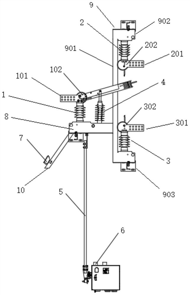
The invention discloses a wall-mounted three-station Internet-surfing isolation switch and a power supply system. The isolation switch comprises a first insulating support column, a second insulating supporting column and a third insulating supporting column, wherein the first insulating supporting column is provided with a first incoming line plate and an isolation moving contact assembly connected with the first incoming line plate; a second incoming line plate and an isolation static contact assembly connected with the second incoming line plate are arranged on the second insulating support column; the third insulating supporting column is arranged opposite to the second insulating supporting column, and a third wire inlet plate and a grounding static contact assembly connected with the third wire inlet plate are arranged on the third insulating supporting column; the isolation moving contact assembly can rotate between the isolation static contact assembly and the grounding static contact assembly, and one of the isolation moving contact assembly and the grounding static contact assembly is selected to be connected with the isolation static contact assembly and the grounding static contact assembly. According to the system, the size of the switch is reduced, so the switch is more suitable for being installed in a rail-mounted area, no on-grid isolation and grounding locking wiring are needed, and on-grid isolation switching-on mistaken power transmission is avoided when the grounding switch is switched on; and a high-definition camera and an electric operating device are adopted, so an action state of the isolating switch can be monitored in real time and remote operation can be performed.

Description

technical field [0001] The invention belongs to the technical field of rail transit power supply, and more specifically relates to a wall-mounted three-station on-line isolating switch and a power supply system. Background technique [0002] The isolating switch is widely used in the subway power supply system, and it is the main stop power transmission device connecting the power supply system of the traction substation and the catenary system. The three-position isolating switch mainly includes isolating static contacts, isolating moving contacts and grounding static contacts, etc. The moving contacts are driven by the linkage mechanism to complete the opening, closing and grounding actions. [0003] The existing rail transit three-position isolating switch has a relatively complex structure and a large volume, and the cable enters and exits from the lower part of the isolating switch, so it is difficult to install it safely and reasonably in the track area; usually it can...

Claims


Application Information

Patent Timeline
Patent Type & Authority Applications(China)
IPC IPC(8): H01H31/00H01H31/02
CPCH01H31/00H01H31/003H01H31/02
Inventor 何俊文王刘辉张栋梁陈国徐鸿燕吴树强何斌吴江涛龚孟荣王开康王璐方刚刘琛
Owner CHINA RAILWAY SIYUAN SURVEY & DESIGN GRP
Learn More