Cable sheath cutter

A technology for cutting tool and cable sheath, which is used in cable installation, cable installation device, and equipment for dismantling/armored cables, etc. It can solve the problems of easy shaking of the cutting cable sheath, uneven depth of the cable sheath, and unstable blade installation. , to achieve the effect of high peeling efficiency, uniform peeling depth and powerful functions

Pending Publication Date: 2018-05-29
广州勇艺邦电子科技有限公司
View PDF7 Cites 4 Cited by
  • Summary
  • Abstract
  • Description
  • Claims
  • Application Information

AI Technical Summary

Problems solved by technology

[0002] When installing or overhauling power cables, it is necessary to peel off the cable sheath (including insulating layer, semi-conductive layer, copper shielding layer, outer sheath, etc.) to connect the line. Traditional cable stripping tools use electrician's knife, hook knife or Tools such as wallpaper knives are used to peel the skin, but because the blades of these knives are not installed firmly, they are easy to shake when cutting the cable skin, and the depth of the cut cable skin is uneven, especially when cutting the semi-conductive layer or copper shielding layer of the cable, due to the semi-conductive Layer and copper shielding layer are relatively thin, it is easy to penetrate the semi-conductive layer or copper shielding layer and destroy its internal structure when cutting, and because the copper shielding layer is relatively hard and the surface is smooth, it is easy to shake during cutting and affect the cutting quality. And there are certain security risks

Method used


Image

  • Cable sheath cutter
  • Cable sheath cutter
  • Cable sheath cutter

Examples


Embodiment Construction

[0020] In order to make the object, technical solution and advantages of the present invention clearer, the present invention will be further described in detail below in conjunction with the accompanying drawings and embodiments. It should be understood that the specific embodiments described here are only used to explain the present invention, not to limit the present invention.

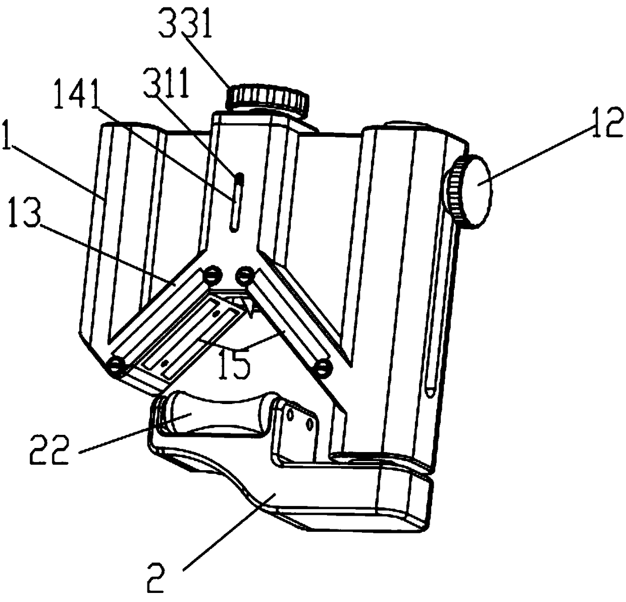
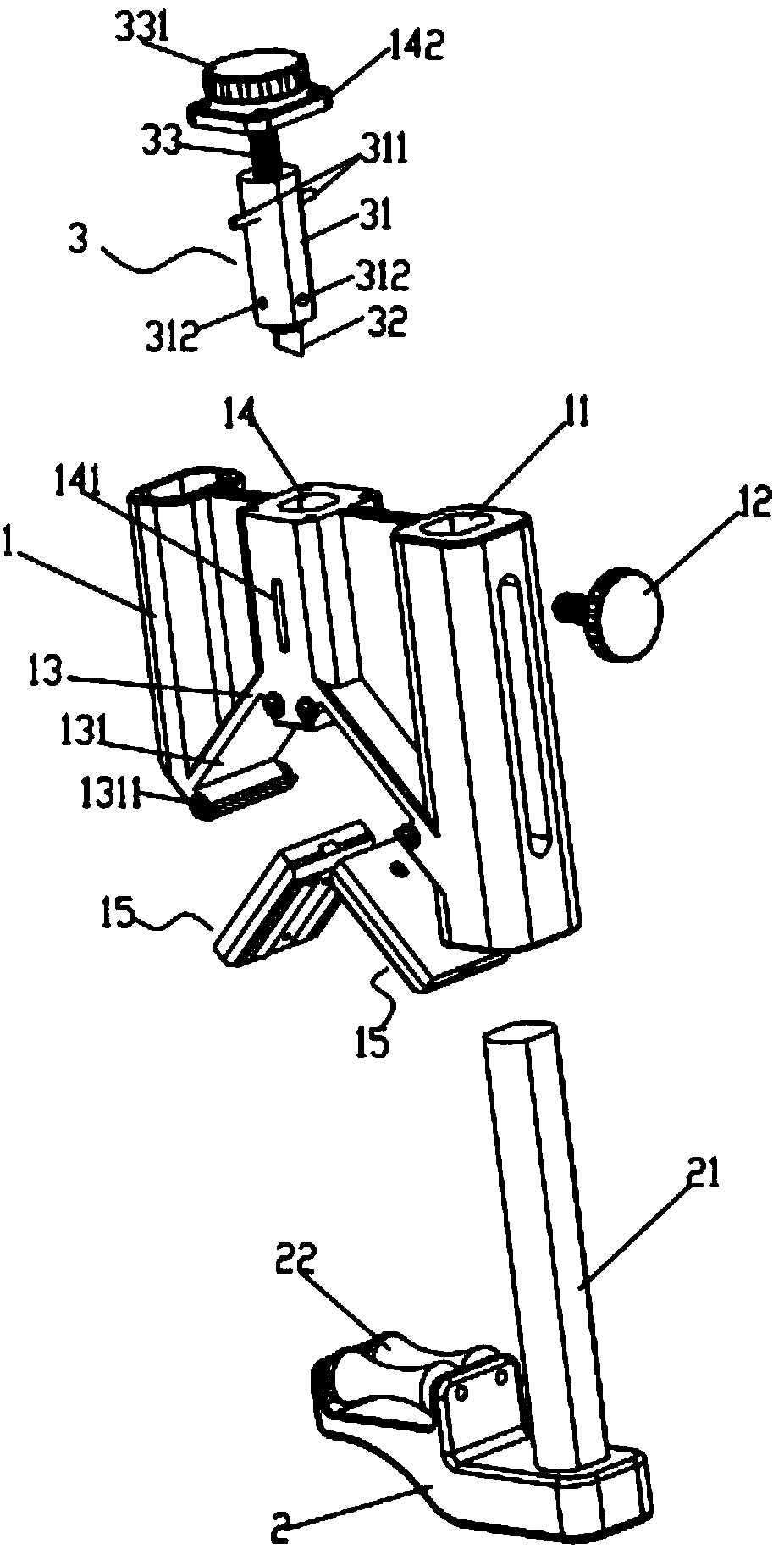
[0021] like Figure 1-2 As shown, the cable sheath cutting tool includes a tool holder 1 and a support seat 2. One side of the tool holder 1 and one side of the support seat 2 are respectively provided with a guide rail channel 11 and a guide rod 21 that cooperate with each other. On the outer wall of the guide rail channel 11 There is a locking knob 12 for locking or loosening the guide rod 21, and an inverted V-shaped support frame 13 opposite to the support seat 2 is provided on the tool holder 1, and the two sides of the support frame 13 and the support seat 2 jointly form a A triangular suppo...


PUM


Abstract

The invention relates to the cable cutter field and especially relates to a cable sheath cutter. The cutter comprises a cutter rest and a cutter head. The cutter rest comprises a handle, a cable support portion and an outer cylinder, wherein the cable support portion and the outer cylinder are arranged on the handle. A cylinder bottom of the outer cylinder is provided with a cutter outlet hole. The cutter outlet hole and the cable support portion are arranged oppositely. The cutter head comprises an inner cylinder, a straight cutter handle, a blade and an adjusting bolt. The inner cylinder isarranged in the outer cylinder and is only rotated. The inner cylinder is provided with an installation hole. The cutter handle is arranged in the installation hole, can only longitudinally move in the installation hole and can not rotate. One end of the cutter handle is fixedly connected to the blade and the other end forms threaded connection with the adjusting bolt. The blade faces towards thecutter outlet hole. A bolt head of the adjusting bolt is rotatably connected to the inner cylinder. The cable sheath cutter is provided with an adjusting structure and a limiting mechanism, wherein the adjusting structure is used for adjusting rotation of the inner cylinder; and the limiting mechanism is used for limiting an inner cylinder rotation position. The cutter has advantages that a peeling depth and an angle are uniform; and the cable sheath cutter can circumferentially cut a cable sheath and can also vertically cut the cable sheath.

Description

technical field [0001] The invention relates to the field of cable cutters, in particular to a cable sheath cutting cutter. Background technique [0002] When installing or overhauling power cables, it is necessary to peel off the cable sheath (including insulating layer, semi-conductive layer, copper shielding layer, outer sheath, etc.) to connect the line. Traditional cable stripping tools use electrician's knife, hook knife or Tools such as wallpaper knives are used to peel the skin, but because the blades of these knives are not installed firmly, they are easy to shake when cutting the cable skin, and the depth of the cut cable skin is uneven, especially when cutting the semi-conductive layer or copper shielding layer of the cable, due to the semi-conductive Layer and copper shielding layer are relatively thin, it is easy to penetrate the semi-conductive layer or copper shielding layer and destroy its internal structure when cutting, and because the copper shielding laye...

Claims


Application Information

Patent Timeline
Patent Type & Authority Applications(China)
IPC IPC(8): H02G1/12
CPCH02G1/126H02G1/1265
Inventor 李孔形杜小建陆刘生陶秀联吴先进许杨瑞陈敬江徐伟林杨向阳覃振海张森林婉霞朱海婷
Owner 广州勇艺邦电子科技有限公司
Why Eureka
Try Eureka