Preparation method for electromotor mounting shell

A technology for installing casings and motors, which is applied in other manufacturing equipment/tools, manufacturing tools, metal processing equipment, etc., can solve the problem of difficulty in ensuring the qualified rate of the finished product size of the stator and rotor installation casings of motors, and eliminate the influence of unstable factors. Improved production efficiency and significant economic benefits

Active Publication Date: 2018-06-01
CHINA HANGFA SOUTH IND CO LTD
View PDF6 Cites 2 Cited by
  • Summary
  • Abstract
  • Description
  • Claims
  • Application Information

AI Technical Summary

Problems solved by technology

The other steps are processed by stamping, which is greatly affected by human factors (manual feeding) in the stamping process of the product, and it is difficult to guarantee the qualified rate of the finished size of the motor stator and rotor installation shell

Method used


Image

  • Preparation method for electromotor mounting shell
  • Preparation method for electromotor mounting shell
  • Preparation method for electromotor mounting shell

Examples


Embodiment Construction

[0038] In order to have a clearer understanding of the technical features, purposes and effects of the present invention, the specific implementation manners of the present invention will now be described with reference to the accompanying drawings. Wherein, the same parts adopt the same reference numerals.

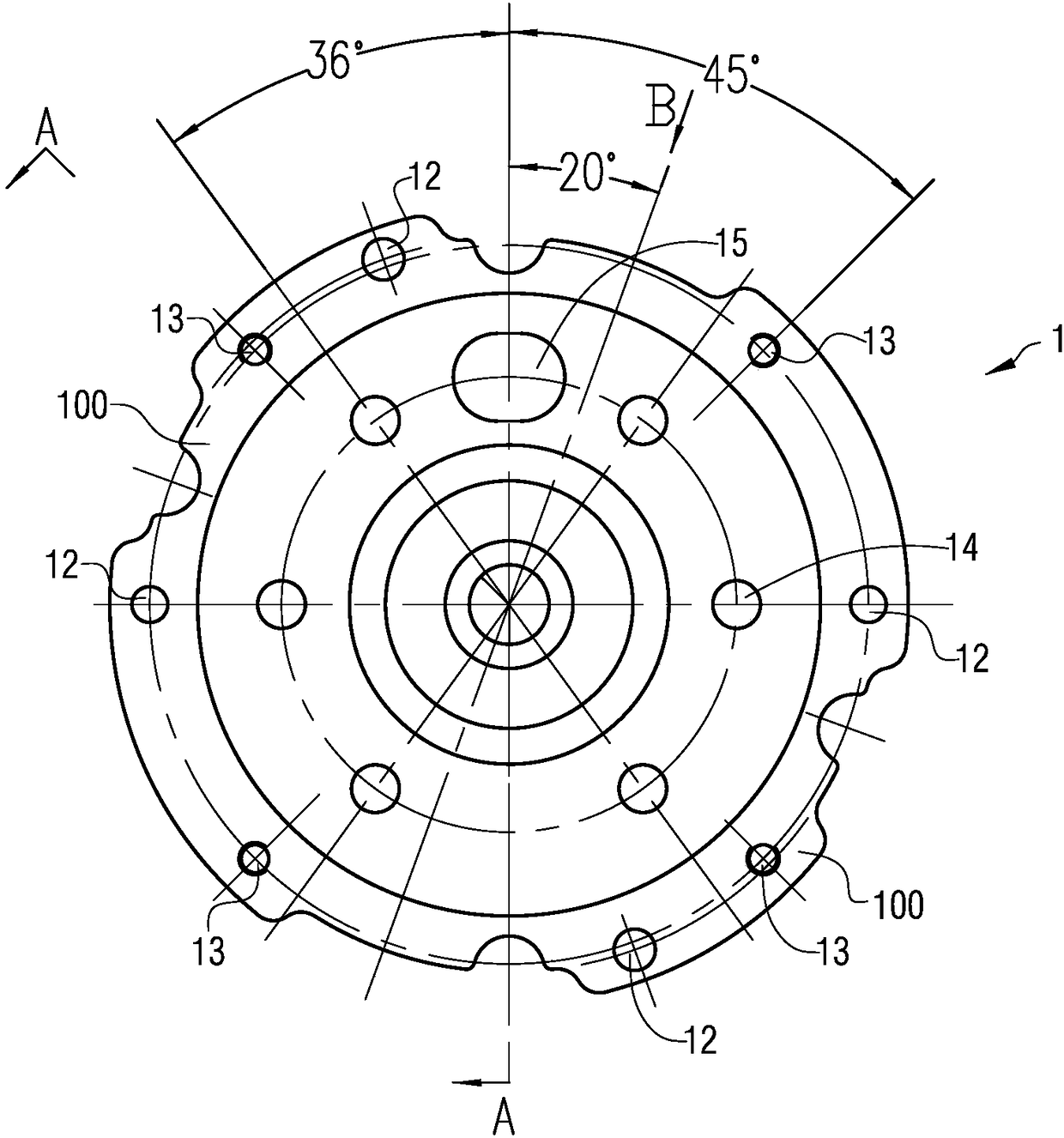
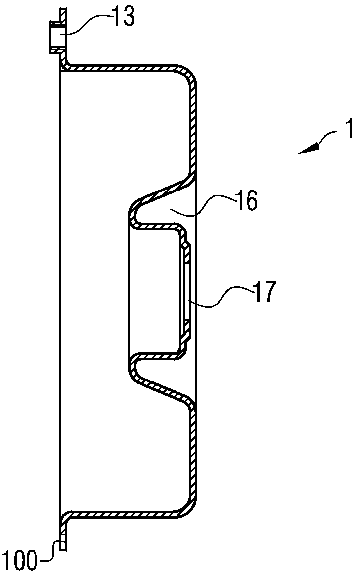
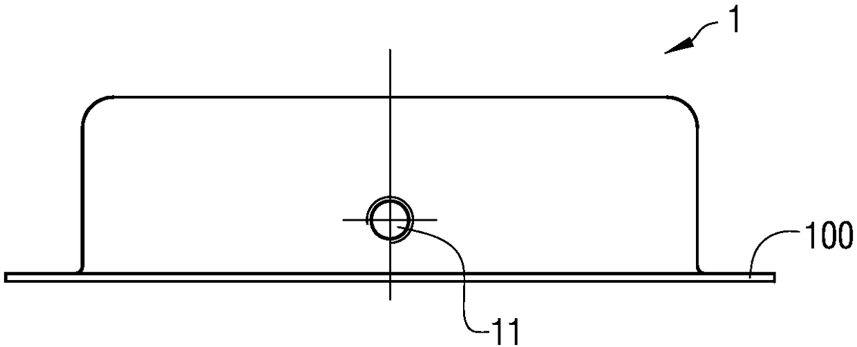
[0039] figure 1 It is a schematic diagram of the structural principle of a motor mounting shell; figure 2 for figure 1 Schematic diagram of the principle of the A-A rotating section structure; image 3 for figure 1 Schematic diagram of the B-direction viewing angle; Figure 4 for figure 1 Schematic diagram of the existing manufacturing process principle of the motor mounting shell; Figure 5 It is a schematic diagram of the production process principle of a method for preparing a motor mounting case according to a specific embodiment of the present invention; Figure 6 for Figure 5 Schematic diagram of the structure and principle of the equipment for the product...


PUM


Abstract

The invention provides a preparation method for an electromotor mounting shell. The preparation method for the electromotor mounting shell comprises the following steps of (A) providing a progressivedie, wherein the progressive die comprises thirteen stations of, sequentially punching a technology gap -> flattening -> first deep drawing -> reverse deep drawing -> second deep drawing -> roughing -> finishing -> punching -> hole flanging -> punching a side opening -> tapping -> blanking -> waste material cutting; (B) conveying a material belt on the progressive die provided by the step (A) andfinishing the operation of punching the side opening when the material belt is conveyed to the station of punching the side opening; (C) finishing the operation of tapping on a horizontal threaded hole when the material belt is conveyed to the station of tapping; and (D) enabling a finished electromotor mounting shell to fall down to finish the preparation when the material belt is conveyed to the station of blanking. By means of the preparation method for the electromotor mounting shell, the unmanned production of a high-accuracy electromotor stator and rotor mounting shell body can be realized and the requirements for punching workers and punching equipment can be greatly reduced.

Description

technical field [0001] The invention relates to the technical field of mechanical manufacturing, in particular to a method for preparing a motor mounting case. Background technique [0002] The motor mounting shell is usually processed from a plate through a punching process. figure 1 It is a schematic diagram of the structural principle of a motor mounting shell; figure 2 for figure 1 Schematic diagram of the principle of the A-A rotating section structure; image 3 for figure 1 Schematic diagram of the B-direction viewing angle; see Figure 1-3 As shown, the motor mounting shell 1 has a relatively complex profile, which is a cylindrical structure with an open bottom, a horizontal threaded hole 11 is provided on the side wall, and a plurality of through holes 12 and stepped threaded holes 13 are provided on the skirt 100, and the skirt 100 A plurality of notches are provided on the outer edge of the side 100 , a mounting hole 14 , a waist-shaped groove 15 and a recess...

Claims


Application Information

Patent Timeline
Patent Type & Authority Applications(China)
IPC IPC(8): B21D37/08B21D35/00B23P23/04
Inventor 罗光炯李展前肖德强
Owner CHINA HANGFA SOUTH IND CO LTD
Why Eureka
Try Eureka