
Mold for membrane insert molding

A technology of insert molding and diaphragm, which is applied in the direction of coating, etc., to achieve the effect of saving materials

Pending Publication Date: 2018-06-01
苏州川鹏塑料有限公司
View PDF6 Cites 0 Cited by
  • Summary
  • Abstract
  • Description
  • Claims
  • Application Information

AI Technical Summary

Problems solved by technology

[0003] The current form of thin-wall high-speed molding can only injection mold battery boxes with a wall thickness of 0.3mm. Research and development is needed to form thinner battery boxes.

Method used


Image

  • Mold for membrane insert molding

Examples


Embodiment Construction

[0017] In order to have a clearer understanding of the technical features, purposes and effects of the present invention, specific implementations are now described in detail.

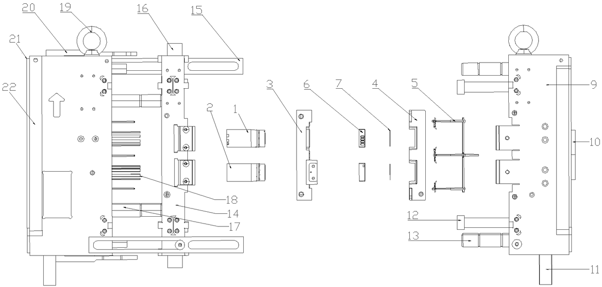
[0018] Such as figure 1 As shown, the mold for diaphragm insert molding includes a mold core and a mold base. The mold core includes a movable mold core 3 and a fixed mold core 4. The first movable mold insert 1 and the second movable mold insert 2 pass through the guide positioning structure Loaded into the frame of the movable mold core 3, the fixed mold insert is loaded into the frame of the fixed mold core 4 through the guiding and positioning structure, the diaphragm 7 is embedded into the end face of the fixed mold insert, fixed by vacuum adsorption, and is formed by the product 6 Wrapped in one.

[0019] The mold base includes a fixed template 9, a first movable template 14 and a second movable template 22. The fixed mold core 4 is positioned in the frame of the fixed template 9 through the ref...


PUM


Abstract

The invention relates to a mold for membrane insert molding. The mold includes mold cores and a mold frame; the mold cores include a movable mold core and a fixed mold core, and a first movable mold insert and a second movable mold insert are inserted into a fame of the movable mold core through a guide positioning structure; a fixed mold insert is inserted into a frame of the fixed mold core through the guide positioning structure, and membranes are embedded into the end surface of the fixed mold insert; the mold frame includes a fixed mold platen, a first movable mold platen, and a second movable mold platen, the fixed mold core is loaded into a frame of the fixed mold platen and is locked by screws, and guide pillars and pull rods are installed on the fixed mold platen; and the movablemold core is loaded into the first movable mold platen, the second movable mold platen is provided with ejector pins, four corners of the second movable mold platen are provided with movable mold guide columns, the first movable mold platen is arranged on the guide columns in a sleeving mode, a shutter is mounted on the first movable mold platen, and pull plates are installed at the diagonal position of two sides of the first movable mold platen and the second movable mold platen. The membranes with the thickness of 0.2mm can be automatically embedded for molding production, and automatic placement, automatic positioning, automatic adsorption, and automatic ejection and demoulding are realized.

Description

technical field [0001] The invention relates to a mold for insert molding of a diaphragm. Background technique [0002] At present, the development of electronic products is changing with each passing day, and people's requirements for products are becoming more and more lightweight, especially mobile phones, cameras, game consoles, etc. Manufacturers have to consider how to maximize battery capacity, minimize volume, and minimize weight. For the production of thin-walled battery boxes, it is necessary to meet the needs of the market and develop thinner, lighter, and larger-capacity battery boxes, which is a very important task at present. [0003] The current form of thin-wall high-speed molding can only injection mold battery boxes with a wall thickness of 0.3mm. Research and development is needed to form thinner battery boxes. Contents of the invention [0004] The purpose of the present invention is to overcome the shortcomings of the prior art and provide a mold for...

Claims


Application Information

Patent Timeline
Patent Type & Authority Applications(China)
IPC IPC(8): B29C45/26B29C45/40B29C45/14
CPCB29C45/14065B29C45/26B29C45/2602B29C45/4005
Inventor 陈胜望吴强
Owner 苏州川鹏塑料有限公司
Learn More