
Shale gas mining system using heat pipe technology

A technology of shale gas exploitation and heat pipe, applied in the direction of exploitation fluid, drill pipe, casing, etc., can solve the problems of polluting groundwater and soil resources, insufficient heat absorption capacity of heat pipe, insufficient heat absorption surface of heat pipe, etc., to save water resources , Improve the utilization of heat source and reduce the development cost

Active Publication Date: 2018-06-01
程煦
View PDF8 Cites 3 Cited by
  • Summary
  • Abstract
  • Description
  • Claims
  • Application Information

AI Technical Summary

Problems solved by technology

However, most of China's shale gas deposits are distributed in Xinjiang, Inner Mongolia, Sichuan and other water-scarce areas, so it is not realistic to use hydraulic drilling technology on a large scale
In addition, hydraulic drilling technology also has potential safety hazards of polluting groundwater and soil resources
[0006] In the prior art, for example, CN106884637A discloses a method for exploiting shale gas using heat pipes, which uses heat pipes to transfer heat from hot dry rock formations to shale gas reservoirs for heating, thereby promoting the exploitation of shale gas. The heat absorption capacity of the heat pipe in the method is insufficient, and in this case only a single gravity heat pipe is arranged up and down, resulting in insufficient heat absorption surface of the heat pipe, and the heat absorption capacity is limited

Method used


Image

  • Shale gas mining system using heat pipe technology
  • Shale gas mining system using heat pipe technology
  • Shale gas mining system using heat pipe technology

Examples


Embodiment Construction

[0038] The specific embodiments of the present invention will be described in detail below in conjunction with the accompanying drawings.

[0039] In this article, if there is no special explanation, when it comes to formulas, " / " means division, and "×" and "*" mean multiplication.

[0040] The specific embodiments of the present invention will be described in detail below in conjunction with the accompanying drawings.

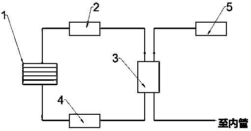
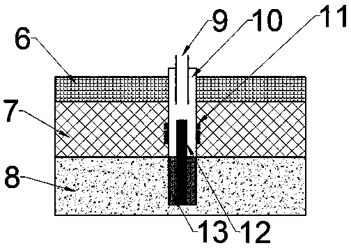
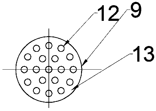
[0041] Such as figure 2 As shown, a shale gas production system using heat pipes, the system includes a steam generator 3, an inner pipe 9 and a casing 10, the inner pipe 9 is sleeved in the casing 10, and the casing 10 is set In the shale gas storage layer 7, the steam generated by the steam generator enters the casing 10 through the inner pipe 9, the heat pipe 12 is arranged in the casing 10, and the perforation hole 11 is arranged on the wall of the casing 10, so The steam is sprayed into the shale gas storage layer 7 through the perforation hole 11, an...


PUM


Abstract

The invention provides a shale gas mining system using a heat pipe technology. The shale gas mining system includes a steam generator, an inner pipe, and a casing pipe. The inner pipe is arranged in the casing pipe in a sleeving mode, and the casing pipe is arranged in a shale gas reservoir; and the steam generated by the steam generator enters the casing pipe through the inner pipe, a heat pipe is disposed in the casing pipe, and split holes are formed on the wall surface of the casing pipe. The shale gas mining system is characterized in that the heat pipe includes a first vertical section,a second vertical section, and a horizontal section; two ends of the horizontal section are separately connected with the first vertical section and the second vertical section, the first vertical section is located in the casing pipe, the horizontal section and the second vertical section are disposed in a dry hot rock formation, and the first vertical section is disposed in the casing pipe; andthe bottom of the first vertical section is connected with the horizontal section, and the horizontal section extends outward along the bottom of the first vertical section. The shale gas mining system using the heat pipe technology adopts a new heat pipe structure and divides the heat pipe into the horizontal section and the vertical sections, the horizontal section is used for expanding the heatabsorption range of the heat pipe, and the utilization of heat is further improved and energy is saved.

Description

technical field [0001] The invention relates to a heat pipe utilization technology, in particular to a shale gas exploitation technology using a heat pipe. Background technique [0002] Shale is a kind of sedimentary rock with complex composition, mainly composed of clay deposits formed by pressure and temperature. Shale gas is a gas mainly composed of methane stored in the nanopores of shale. Shale gas is mostly stored in shale in a free state and an adsorbed state, and there are significant differences in the proportions of these two forms of shale gas under different geological conditions. The larger the pore size of shale, the more free shale gas can be stored, and the higher the organic matter content of shale, the more adsorbed shale gas can be stored. Most of the existing shale gas is stored at a depth of 1-2 kilometers underground (the pressure is about 10-20MPa, and the temperature is about 338-378K). [0003] Shale gas is mainly composed of methane and is an imp...

Claims


Application Information

Patent Timeline
Patent Type & Authority Applications(China)
IPC IPC(8): E21B43/24E21B17/00
CPCE21B17/00E21B43/24
Inventor 程煦
Owner 程煦
Learn More