
Heat energy recovery equipment for heat energy and power engineering and use method

A power engineering and heat energy recovery technology, applied in the field of heat energy and power engineering, can solve the problems that the range cannot be adjusted when absorbing heat energy, and the steps are cumbersome and inconvenient when disassembling and replacing.

Inactive Publication Date: 2021-09-07
LIAONING TECHNICAL UNIVERSITY
View PDF0 Cites 0 Cited by
  • Summary
  • Abstract
  • Description
  • Claims
  • Application Information

AI Technical Summary

Problems solved by technology

[0005] Aiming at the deficiencies of the prior art, the present invention provides heat energy recovery equipment for thermal energy and power engineering and its use method, which has the advantages of easy replacement of the internal filter plate of the heat energy recovery equipment and easy adjustment of the range when absorbing heat energy, etc., which solves the problem of traditional heat energy recovery The steps of the recovery device are cumbersome and inconvenient when disassembling and replacing the internal filter plate, and the range is fixed and cannot be adjusted when absorbing heat energy

Method used


Image

  • Heat energy recovery equipment for heat energy and power engineering and use method
  • Heat energy recovery equipment for heat energy and power engineering and use method
  • Heat energy recovery equipment for heat energy and power engineering and use method

Examples


Embodiment Construction

[0026] The following will clearly and completely describe the technical solutions in the embodiments of the present invention with reference to the accompanying drawings in the embodiments of the present invention. Obviously, the described embodiments are only some, not all, embodiments of the present invention. Based on the embodiments of the present invention, all other embodiments obtained by persons of ordinary skill in the art without making creative efforts belong to the protection scope of the present invention.

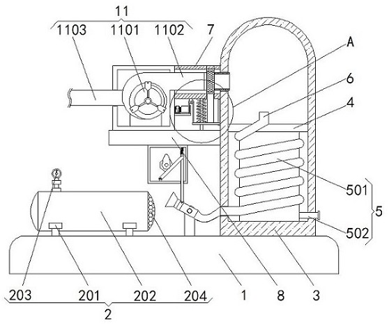
[0027] see Figure 1-3, heat energy recovery equipment for thermal energy and power engineering and its use method, including a base 1, a power assembly 2 is arranged on the top of the base 1, the power assembly 2 includes a mounting frame 201, and the mounting frame 201 is fixedly connected to the top of the base 1, and the number of mounting frames 201 is Two and distributed symmetrically on the left and right. The top of the left mounting frame 201 is fixed...


PUM


Abstract

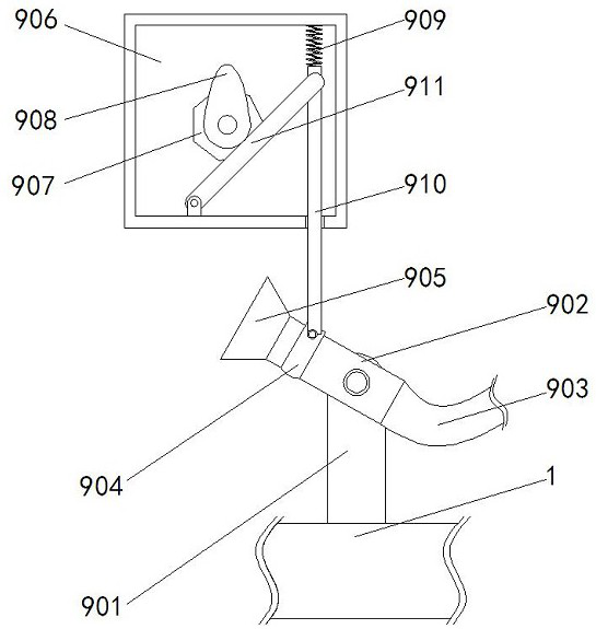
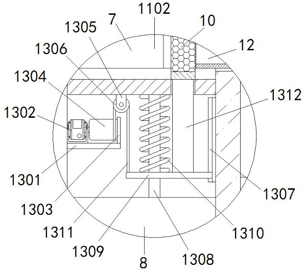
The invention relates to the technical field of heat energy and power engineering, and discloses heat energy recovery equipment for heat energy and power engineering and a use method. The heat energy recovery equipment comprises a base, a power assembly is arranged at the top of the base, a heat collection barrel located on the right side of the power assembly is fixedly connected to the top of the base, and a partition plate is arranged between the left side and the right side of the inner wall of the heat collection barrel; and a water storage assembly with one end penetrating and extending to the right side of the heat collection barrel is arranged between the bottom of the inner wall of the heat collection barrel and the partition plate, and a spiral heat exchange pipe with one end penetrating and extending to the left side of the heat collection barrel and the other end penetrating and extending to the top of the partition plate is arranged on the outer side of the water storage assembly. According to the heat energy recovery equipment for the heat energy and power engineering and the use method, a servo motor is started to drive a rope drum to rotate, a pull rope is wound when the rope drum rotates, the pull rope pulls a lifting plate to move upwards, a jacking rod pushes a filter plate to move out of the top of a filter pipe while the lifting plate moves upwards, and therefore workers can replace the filter plate conveniently.

Description

technical field [0001] The invention relates to the technical field of heat energy and power engineering, in particular to heat energy recovery equipment and a use method for heat energy and power engineering. Background technique [0002] "Thermal energy and power engineering" is a synthesis of various science and technology, including modern energy science and technology, information science and technology and management technology, etc., mainly involves the design, operation, automatic control, information processing, computer application, Environmental protection, refrigeration and air conditioning, efficient and clean utilization of energy, and development of new energy. [0003] In thermal energy and power engineering operations, when the engine releases power, it will emit a large amount of exhaust heat energy. The lost heat energy not only causes a waste of resources, but also increases the temperature of the workshop and affects the working environment of workers. T...

Claims


Application Information

Patent Timeline
IPC IPC(8): F28D7/02F28F9/00F28F19/01F22B1/18F22B31/08F22D11/06
CPCF28D7/024F28F9/00F28F19/01F22B1/18F22B31/08F22D11/06
Inventor 李文华张政李婷婷
Owner LIAONING TECHNICAL UNIVERSITY
Learn More