Novel tubular conveyer belt rebound force measuring device and measuring method thereof

A technology for measuring devices and conveyor belts, applied in measuring devices, force/torque/work measuring instruments, instruments, etc., can solve the problems of inconvenient industrial field measurement, inaccurate measurement results, large occupied area, etc., and achieve simple technical means Ease of operation, high measurement accuracy and low cost

Pending Publication Date: 2018-06-01
SOUTH CHINA UNIV OF TECH
View PDF4 Cites 2 Cited by
  • Summary
  • Abstract
  • Description
  • Claims
  • Application Information

AI Technical Summary

Problems solved by technology

[0003] At present, the measuring device of the tubular conveyor belt is mainly vertical. This measurement method places the sample of the circular tubular conveyor belt horizontally, and the measured rebound force will introduce the gravity interference of the conveyor belt itself, making the measurement result inaccurate.
Although some measuring devices can simulate the working conditions of the conveyor belt, they occupy a large area and are difficult to move, making it inconvenient to measure on the industrial site

Method used


Image

  • Novel tubular conveyer belt rebound force measuring device and measuring method thereof
  • Novel tubular conveyer belt rebound force measuring device and measuring method thereof
  • Novel tubular conveyer belt rebound force measuring device and measuring method thereof

Examples


Embodiment

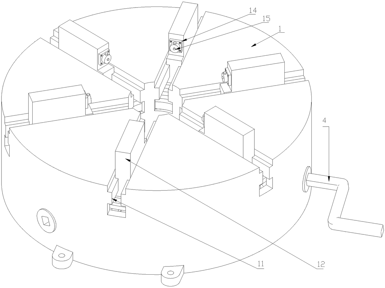
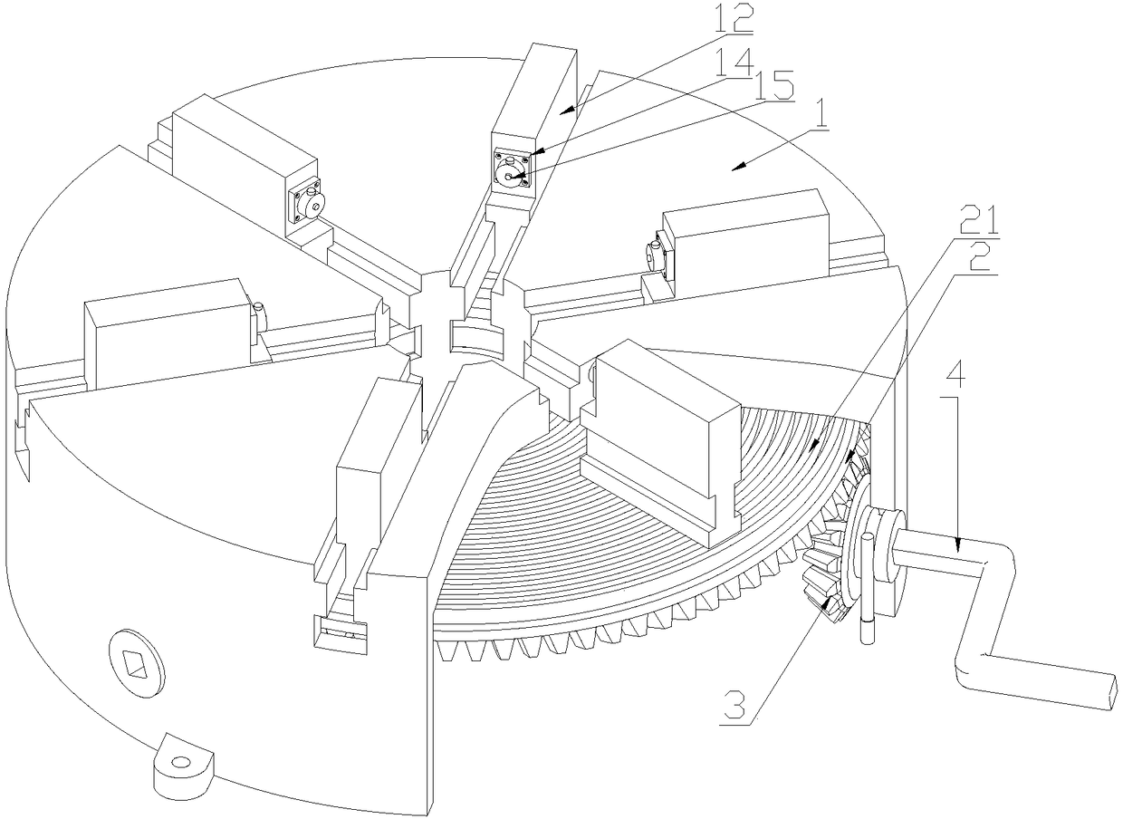
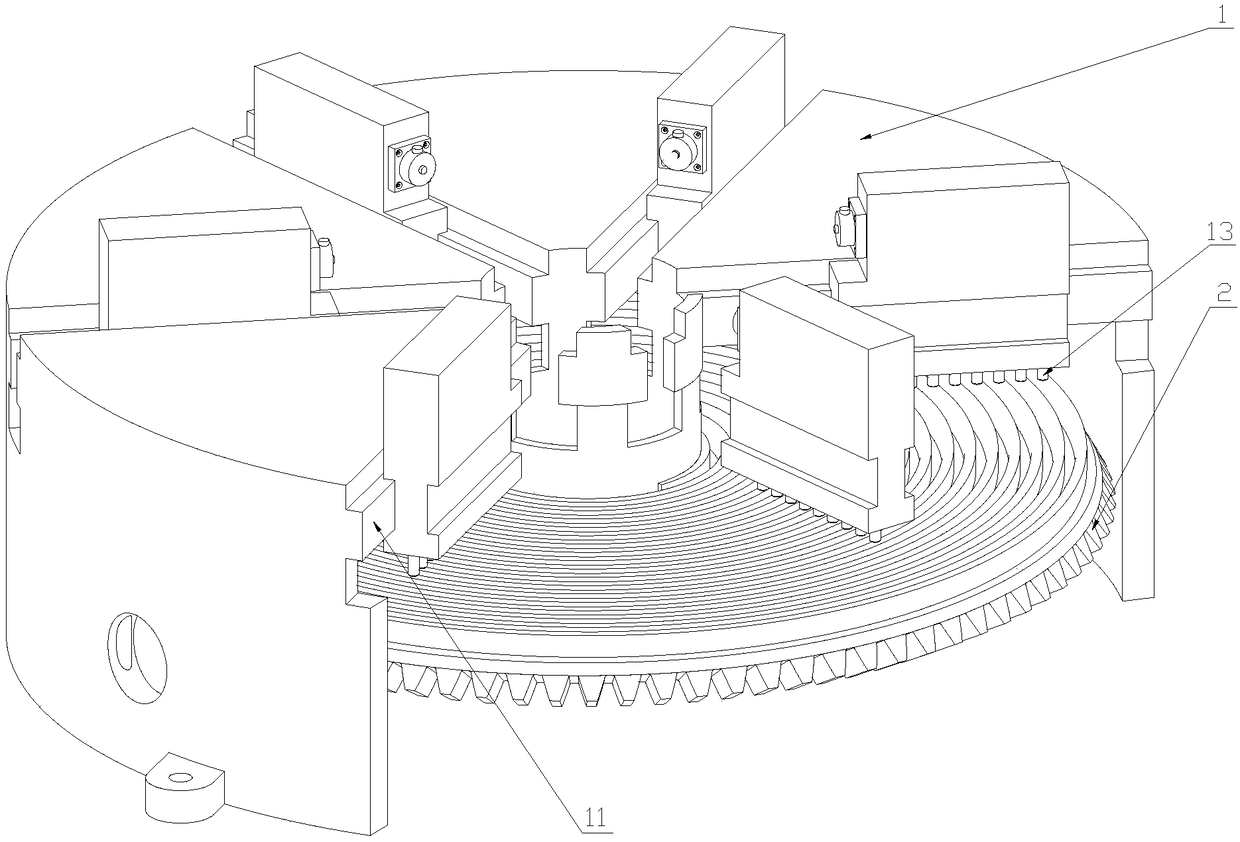
[0032] Such as Figure 1-6 Shown. The invention discloses a new type of tube-type conveyor belt rebound force measuring device, which comprises a chuck shell 1 and a bevel gear disk 2 coaxially installed in the chuck shell 1;

[0033] The upper end surface of the bevel gear plate 2 is provided with a plane thread groove 21;

[0034] A plurality of clamping grooves 11 with the same structure are symmetrically opened along the radial direction of the chuck housing 1, and each clamping groove 11 is provided with a clamping claw 12 with the same structure, and each clamping claw 12 is restricted in the clamping On the groove 11, it can slide in the groove 11; on the lower side of the clamping jaw 12, there are a plurality of pins 13 that mesh with the plane thread groove 21 at equal intervals; when the bevel gear plate 2 rotates, the clamping Pushed by the flat thread groove 21, the jaws 12 move synchronously at equal intervals along the track of the groove 11 toward the center or th...


PUM


Abstract

The invention discloses a novel tubular conveyer belt rebound force measuring device and a measuring method thereof. The device comprises a chuck shell and a bevel gear disc coaxially arranged in thechuck shell. A planar threaded groove is formed in the upper end surface of the bevel gear disc. A plurality of clamping grooves of the same structure are symmetrically formed in the radial directionof the chuck shell. A clamping jaw of the same structure is arranged in each clamping groove. Each clamping jaw is limited in the corresponding clamping groove and can slide in the clamping groove. Aplurality of pin shafts meshed with the planar threaded groove are distributed on the lower sides of the clamping jaws at equal intervals. When the bevel gear rotates, the clamping jaws are pushed bythe planar threaded groove to synchronously move towards the center / outer peripheral direction of the chuck shell along the tracks of the clamping grooves. In this way, the size of the circumference of each clamping jaw can be changed. The invention has the advantages of simple and feasible technical means, light and portable size, low manufacturing cost, simple and convenient operation during themeasurement process, and high measurement precision. The device and the method provide positive and effective application data for the model selection of circular and tubular conveyer belts.

Description

Technical field [0001] The present invention relates to rubber rebound force measurement, in particular to a new type of tube conveyor belt rebound force measurement device and measurement method. Background technique [0002] Tubular conveyor belt is a kind of closed conveyor belt, which can reduce material leakage during transportation, avoid environmental pollution, and prevent material pollution and deterioration. The tube-shaped conveyor belt can also realize the change of direction transportation in space, and has been widely used in recent years. However, if the rebound force of the tubular conveyor belt is not selected properly, it will damage the rollers and other components and affect the transportation effect. Therefore, the rebound force of the conveyor belt must be measured so that the force of the roller is in the normal working range. [0003] At present, the measuring device of the tubular conveyor belt is mainly vertical. This measuring method makes the sample of...

Claims


Application Information

Patent Timeline
IPC IPC(8): G01L5/00
CPCG01L5/0061
Inventor 杜群贵赖泽豪
Owner SOUTH CHINA UNIV OF TECH
Why Eureka
Try Eureka