Automatic fitting fixture of connector

A connector and tooling technology, which is applied in the field of connector automatic pressing tooling, can solve the problems of not being able to adapt to the needs of intelligent continuous production, low degree of automation, and high labor intensity of workers

Active Publication Date: 2018-06-01
江苏华兴通讯科技有限公司
View PDF5 Cites 4 Cited by
  • Summary
  • Abstract
  • Description
  • Claims
  • Application Information

AI Technical Summary

Problems solved by technology

[0002] The cable connector is generally composed of an inner conductor installed inside the outer shell through an insulator. The inner cavity of the outer shell and the outer surface of the insulator, the inner hole of the insulator and the inner conductor are fixed by interference fit, and the outer shell and the insulator, the insulator and the There are barbed structures between the inner conductors, so that the outer shell, insulator, and inner conductor cannot be plugged and fixed at the same time. When assembling traditional cable connectors, the outer shell is generally inserted into the foam box upside down with the small end facing down. After inserting the insulator and inner conductor into the outer casing, press the insulator into the outer casing through the machine tool, then take out the product and transfer it to another machine tool to press the inner conductor into the insulator. Manual guidance is required when the insulator and inner conductor are inserted into the outer casing. Positively, the transfer station also needs to be completed manually, the operation is cumbersome, the labor intensity of the workers is high, and the degree of automation is low, which cannot meet the needs of intelligent continuous production. Combination causes product scrapping, increases cost consumption, and reduces production efficiency

Method used


Image

  • Automatic fitting fixture of connector
  • Automatic fitting fixture of connector
  • Automatic fitting fixture of connector

Examples


Embodiment Construction

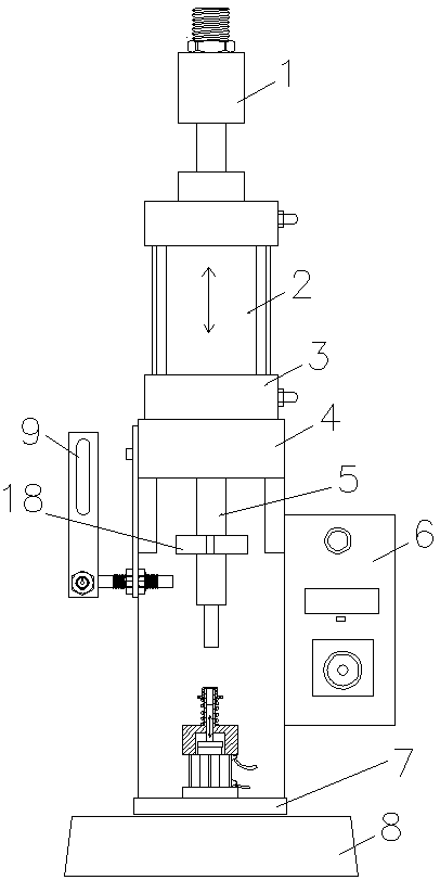
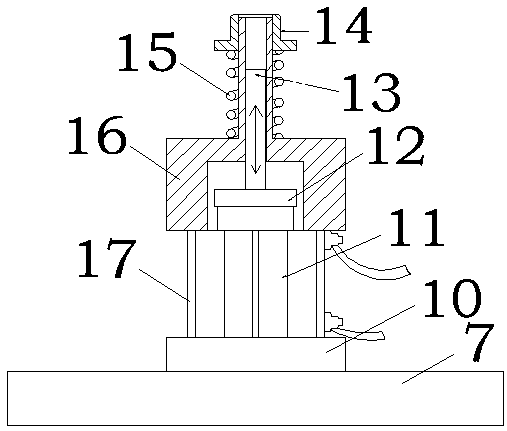
[0019] As shown in the figure, a connector automatic pressing tooling includes a base 8 on which a lower mold is installed through a lower mold base 7 and an upper mold is installed through a mold frame. The lower mold includes a fixing plate 10 above which A lower template 16 is installed through the lower mold column 17. The lower template 16 has a lower mold cavity inside, and a lower mold core 13 is arranged in the lower mold cavity. The top of the lower template 16 has an upwardly protruding top column, and the inside of the top column is hollow to form a lower mold. hole, the lower mold hole communicates with the lower mold cavity; the lower mold core cylinder 11 is installed between the lower template 16 and the fixed plate 10, the top of the lower mold core cylinder 11 extends into the lower mold cavity, and the lower mold core 12 is fixed by the mounting plate 12 Installed on the top of the telescopic rod of the lower mold core cylinder 11 and can be driven by the lowe...


PUM


Abstract

The invention discloses an automatic fitting fixture of a connector, wherein after being arranged in an insulator in a sleeving manner, an inner conductor is placed into a lower mold hole in the top of a lower mold pillar on a lower mold plate, the bottom end of the insulator is limited by the top end of the lower mold pillar, an outer shell is placed on a product carrier on the top of the lower mold pillar on the lower mold plate, after passing through an upper mold base, an expansion link of a fitting cylinder drives an upper mold pressing rod to move downwards, the upper mold pressing rod presses the outer shell to push the product carrier to move downwards along the lower mold pillar, the insulator is limited by the top end of the lower mold pillar to keep still, and thus the insulatoris embedded into the outer shell; a time relay controls the upper mold pressing rod to be retreated back after staying for a while, and controls a lower mold core cylinder via a sensing switch to drive a lower mold core to move upwards, and the top end of the lower mold core to prop up an inner conductor so as to be upwards inserted into the insulator; therefore, the automatic fitting can be completed, the production cost and investment can be reduced, and the production efficiency can be improved.

Description

technical field [0001] The invention relates to an automatic press-fit tooling for a connector. Background technique [0002] The cable connector is generally composed of an inner conductor installed inside the outer shell through an insulator. The inner cavity of the outer shell and the outer surface of the insulator, the inner hole of the insulator and the inner conductor are fixed by interference fit, and the outer shell and the insulator, the insulator and the There are barbed structures between the inner conductors, so that the outer shell, insulator, and inner conductor cannot be plugged and fixed at the same time. When assembling traditional cable connectors, the outer shell is generally inserted into the foam box upside down with the small end facing down. After inserting the insulator and inner conductor into the outer casing, press the insulator into the outer casing through the machine tool, then take out the product and transfer it to another machine tool to pres...

Claims


Application Information

Patent Timeline
Patent Type & Authority Applications(China)
IPC IPC(8): H01R43/20
CPCH01R43/20
Inventor 宋小江
Owner 江苏华兴通讯科技有限公司
Why Eureka
Try Eureka