A fast design method for rotor tooth width of bearingless flux switching motor

A technology of magnetic flux switching motor and design method, applied in the direction of magnetic circuit rotating parts, magnetic circuit shape/style/structure, etc., can solve the problem of blind selection of initial rotor tooth width, time-consuming increase of rotor tooth width, and published research results. and other problems, to achieve the effect of less calculation amount and calculation time, reducing the pulsation amplitude and increasing the output capacity

Active Publication Date: 2019-06-04
FUZHOU UNIV
View PDF5 Cites 0 Cited by
  • Summary
  • Abstract
  • Description
  • Claims
  • Application Information

AI Technical Summary

Problems solved by technology

Obviously, the disadvantages of this method are: (1) the finite element calculation takes a long time; (2) the selection of the initial rotor tooth width in the finite element analysis is blind, which brings about a further increase in the time spent on optimizing the rotor tooth width by finite element analysis
How to quickly optimize the rotor tooth width according to the new requirements of this optimization goal has become the key to the design of bearingless flux switching motors, and no research results in this area have been published yet.

Method used


Image

  • A fast design method for rotor tooth width of bearingless flux switching motor
  • A fast design method for rotor tooth width of bearingless flux switching motor
  • A fast design method for rotor tooth width of bearingless flux switching motor

Examples


Embodiment Construction

[0034] The technical solution of the present invention will be specifically described below in conjunction with the accompanying drawings.

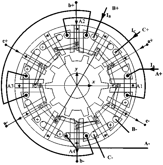
[0035] A method for quickly designing the rotor tooth width of a bearingless flux switching motor provided by the present invention provides a bearingless flux switching motor structure with three-phase suspension windings. Its basic structure is similar to that of a three-phase flux switching permanent magnet motor, and its stator is composed of It is composed of 12 U-shaped iron core punches, and a permanent magnet is sandwiched between two adjacent U-shaped iron core punches. The inner side of the stator is provided with suspension windings a, b, c; the implementation steps of this method are as follows,

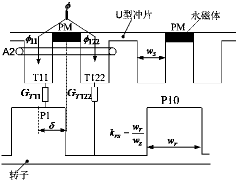
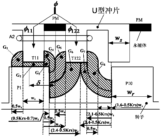
[0036] Step S1. According to the design theory of flux switching motor or AC motor, the stator tooth width is determined, and the stator slot width is the same as the stator tooth width;

[0037] Step S2. Determine the air gap lengt...


PUM


Abstract

The invention relates to a rapid design method for a rotor tooth width of a bearing-free magnetic flux switching motor. By optimal design of the rotor tooth width, maximum counter electromotive forceamplitude of a power winding is achieved, so that minimum ampere turns of the power winding in a limited stator groove space is achieved, maximum ampere turns of a suspension winding is achieved, theoutput of a rotor suspension force is remarkably improved, and the pulse of the suspension force is reduced. By the method, a few calculation resources are required, low calculation quantity and shortcalculation consumption time are required, the ampere turns of the power winding in a stator groove is reduced to the greatest extent, the output capability of the suspension force is remarkably improved, and the pulse amplitude of the suspension force is obviously reduced.

Description

technical field [0001] The invention relates to a method for quickly designing the rotor tooth width of a bearingless magnetic flux switching motor. Background technique [0002] The permanent magnet of the bearingless flux switching motor (BFSPMM) is located on the stator, and the rotor is a salient pole iron core, so the heat of the permanent magnet of the motor is easy to dissipate, and there is no risk of permanent magnet demagnetization. At the same time, the slots for embedding the windings are also located on the stator. Using the characteristic that the reluctance between the two teeth of the stator and rotor changes with the change of the rotor position, a sine wave back electromotive force is generated in the stator power winding. In order to further realize the floating operation of the rotor, it is necessary to embed the floating winding on the stator, so that the power winding and the floating winding are embedded on the stator at the same time. In order to gen...

Claims


Application Information

Patent Timeline
Patent Type & Authority Patents(China)
IPC IPC(8): H02K1/24
CPCH02K1/24
Inventor 周扬忠方飞吴汉童钟天云
Owner FUZHOU UNIV
Why Eureka
Try Eureka