Rolling mill stand roller replacing device

A technology for rack rolls and rolling mills, which is applied in the direction of metal rolling racks, metal rolling mill stands, lifting devices, etc., and can solve problems such as inability to construct maintenance items, difficult disassembly, and small lower positions of the rolls, so as to reduce unplanned downtime Time, avoid rack roller failure, ensure the effect of installation position

Active Publication Date: 2018-06-05
BAOSHAN IRON & STEEL CO LTD
View PDF5 Cites 5 Cited by
  • Summary
  • Abstract
  • Description
  • Claims
  • Application Information

AI Technical Summary

Problems solved by technology

[0010] 1. The pressing force of the inclined wedge is relatively large, and the rollers of the frame cannot be lifted out. Multiple guide chains are needed to adjust the position, and the lower part of the rollers is small. It is difficult to find a suitable jack and a suitable position, and the processing time is long. Disassembly difficulty;
[0011] 2. After the rack rollers are removed, it is necessary to use multiple guide chains to lead out, and multiple personnel should pay attention to the positions, etc. The situation of crooked pulling and slanting lifting occurs from time to time, and the safety problem is prominent; at the same time, it is necessary to cooperate with the lifting by driving. During the period, other Maintenance projects using driving vehicles cannot be constructed, which consumes a lot of manpower and material resources

Method used


Image

  • Rolling mill stand roller replacing device
  • Rolling mill stand roller replacing device
  • Rolling mill stand roller replacing device

Examples


Embodiment Construction

[0031] Specific embodiments of the present invention will be further described in detail below in conjunction with the accompanying drawings.

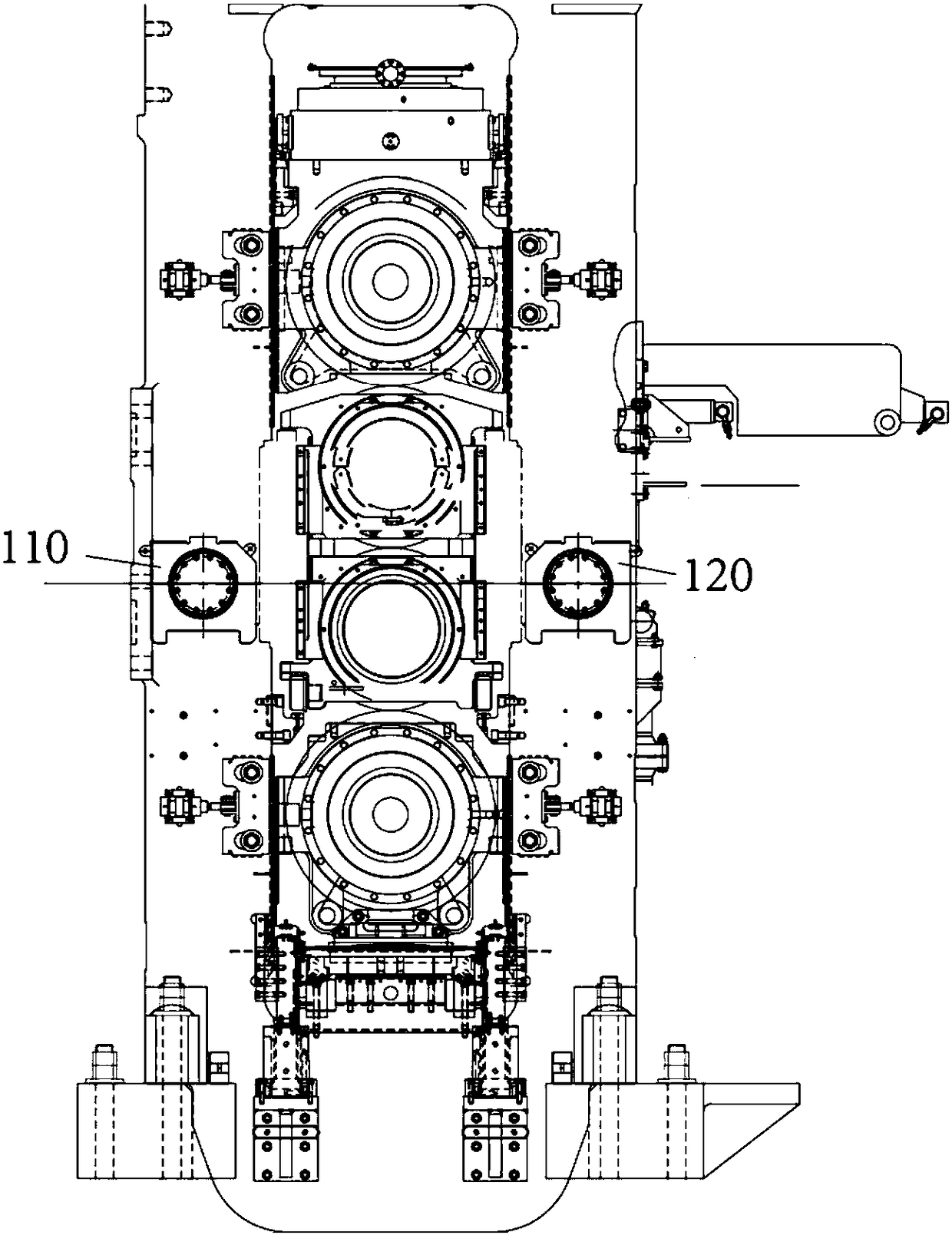
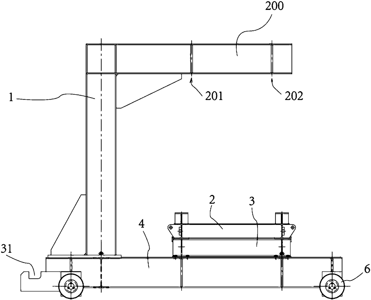
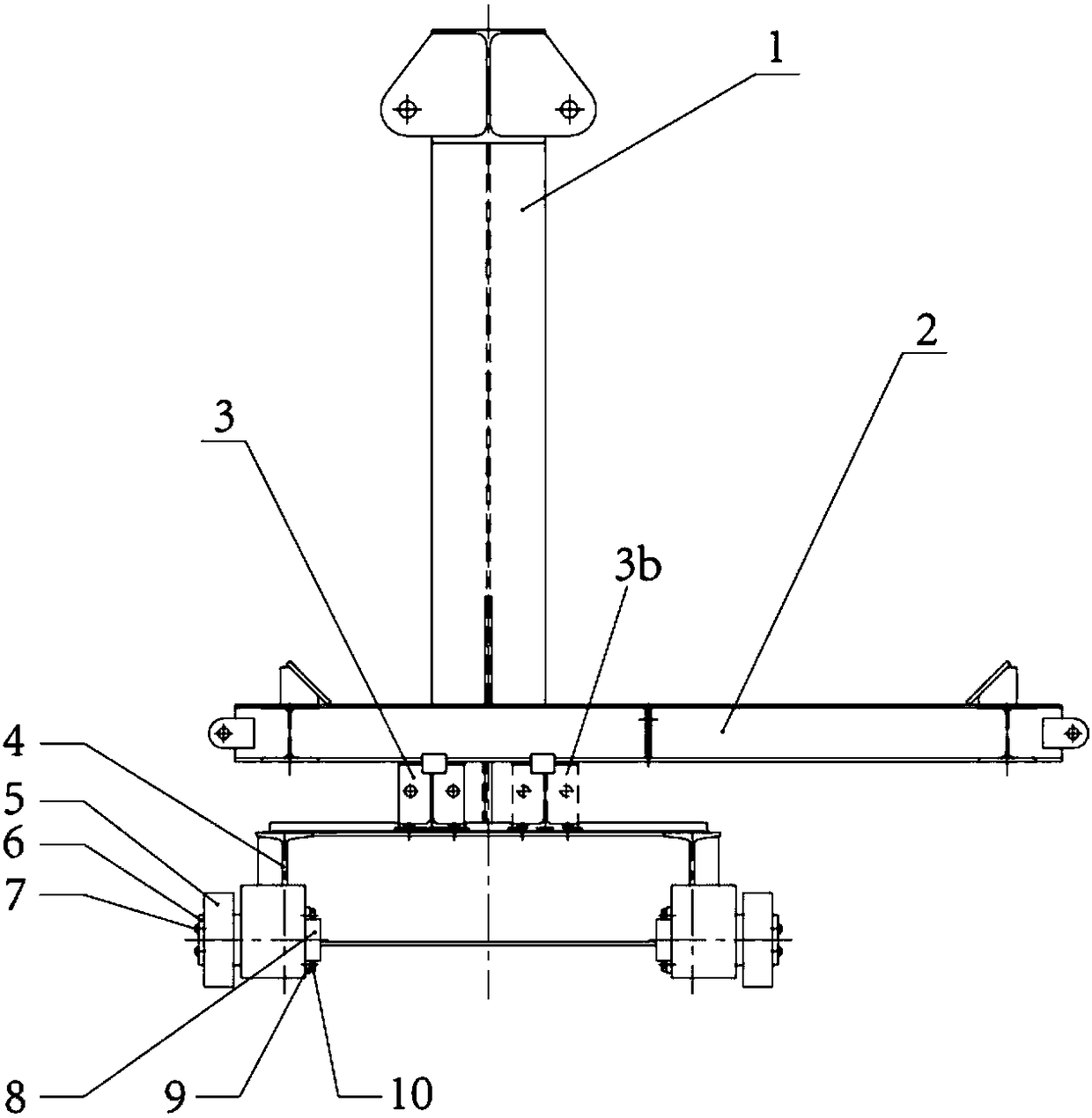
[0032] Such as Figure 2 to Figure 7 The shown rolling mill stand roll replacement device and its application schematic structure, the figure schematically shows the rolling mill right stand roll replacement process.

[0033] The main body of the rack roll replacement device provided by the present invention is a crane 300 that can be put in and out of the rolling mill, which includes a C-shaped right-angle frame 1, which includes a crossbeam 200, and the C-shaped opening of the right-angle frame 1 faces the tail of the crane . The right angle frame 1 is placed on the base 4, the base 4 is provided with a joist 3, and the joist 3 can move back and forth along the chute arranged on the base 4 in the horizontal direction (or it can also be set that the bracket 2 moves along the joist 3 The chute on the top moves back and forth along th...


PUM


Abstract

The invention provides a rolling mill stand roller replacing device. The device comprises a crane capable of going into and out of a rolling mill, and the traveling track of the crane is parallel to aroller shaft of a stand roller to be replaced; a supporting beam is arranged on a base of the crane, and is provided with a sliding rail which allows a supporting frame to horizontally slide along the sliding rail, the sliding rail is perpendicular to the traveling track of the crane, and a suspension beam is arranged at the top of the crane; and the device further comprises the supporting framewhich can be placed in the rolling mill and is supported by the supporting beam of the crane entering the rolling mill, lifting lugs or hanging holes are formed in the peripheral ends of the supporting frame; and a supporting rotating shaft with changeable rotating positions is arranged at the position, opposite to the supporting frame, of the supporting beam, and an avoiding space capable of preventing interference with guide and guard plates in the rolling mill is formed in a frame body of the supporting frame.

Description

technical field [0001] The invention relates to a device for disassembling and replacing stand rolls at the entrance and exit of a rolling mill. Background technique [0002] The 1580 rolling mill stand roll is an important part of the rolling line, and the R1 and R2 rolling mills each have two, such as figure 1 As shown, the rolling mill rolls 110 and 120 are located at the entrance and exit sides of the rolling mill, and the rack rolls are the key components of the rolling mill. The rack rolls of this machine are located inside the rolling mill, and the installation opening is 1920. Since the 1580 rolling mill was designed in Japan, It is very compact in structure, so it is very difficult to disassemble and replace. During the replacement process, it will cause faults caused by the installation of the rack rollers, and the processing time of the faults is relatively long. [0003] This is because the rack rolls are installed inside the rolling mill, and there are upper an...

Claims


Application Information

Patent Timeline
Patent Type & Authority Applications(China)
IPC IPC(8): B21B31/12B66D3/00B66F7/20
CPCB21B31/12B21B2203/32B66D3/00B66F7/20
Inventor 谢明张仁其陈淞陆智翔
Owner BAOSHAN IRON & STEEL CO LTD
Why Eureka
Try Eureka