Axial flow compressor circumferential-direction large-interval small-through-hole cartridge receiver

An axial flow compressor, large interval technology, applied in the direction of machine/engine, mechanical equipment, liquid fuel engine, etc., can solve the problems of increasing engine weight and cost, complex pipeline structure and control valve, obvious mainstream influence, etc. The effect of convenient application implementation and simple structure

Active Publication Date: 2018-06-05
NANJING UNIV OF AERONAUTICS & ASTRONAUTICS
View PDF5 Cites 2 Cited by
  • Summary
  • Abstract
  • Description
  • Claims
  • Application Information

AI Technical Summary

Problems solved by technology

The former has been researched by many scholars, and a variety of control methods have been designed to effectively increase the stability margin, such as constant air injection at the blade tip. At the same time, the efficiency of the compressor will be reduced, and complex pipeline structures and control valves are required, which increases the weight and cost of the engine

Method used


Image

  • Axial flow compressor circumferential-direction large-interval small-through-hole cartridge receiver
  • Axial flow compressor circumferential-direction large-interval small-through-hole cartridge receiver
  • Axial flow compressor circumferential-direction large-interval small-through-hole cartridge receiver

Examples


Embodiment 1

[0026] Example 1 (take Rotor37 rotor parameters as an example)

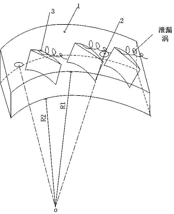
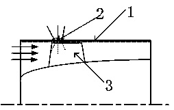
[0027] The casing of the axial flow compressor has large intervals and small through holes in the circumferential direction, and its structure includes a casing 1, a through hole 2, and a rotor 3; the casing 1 is cylindrical, and the through hole 2 is located on the outer surface of the casing 1, directly connected to the The external environment of the casing 1 is connected to the atmosphere, and several rotors 3 are arranged in the hollow interior of the casing 1 .

[0028] There are N1 through-holes 2, which are set around the surface of the casing 1 at the short distance L1 between the inlet of the rotor impeller and the leading edge of the blade. The number of through-holes 2 is selected with reference to the number of blades of the axial flow compressor, and the number of blades of the compressor is Z , known Z=36, N1 / Z is 0.5, then N1=18.

[0029] The gauge pressure of the internal flow field of the compr...

Embodiment 2

[0032] Example 2 (take Rotor37 rotor parameters as an example)

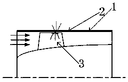
[0033] The casing of the axial flow compressor has large intervals and small through holes in the circumferential direction, and its structure includes a casing 1, a through hole 2, and a rotor 3; the casing 1 is cylindrical, and the through hole 2 is located on the outer surface of the casing 1, directly connected to the The external environment of the casing 1 is connected to the atmosphere, and several rotors 3 are arranged in the hollow interior of the casing 1 .

[0034] There are N1 through-holes 2, which are set around the surface of casing 1 at the long distance L2 between the inlet of the rotor impeller and the leading edge of the blade. The number of through-holes 2 is selected with reference to the number of blades of the axial flow compressor, and the number of blades of the compressor is Z , known Z=36, N1 / Z is 0.5, then N1=18.

[0035] The gauge pressure of the internal flow field of the compressor...


PUM


Abstract

The invention relates to an axial flow compressor circumferential-direction large-interval small-through-hole cartridge receiver. The axial flow compressor circumferential-direction large-interval small-through-hole cartridge receiver is structurally comprises a cartridge receiver body, a through hole and a rotor; the through hole is formed in the outer surface of the cartridge receiver and directly connected to ambient atmosphere outside the cartridge receiver, and the rotor is arranged inside the cartridge receiver; air at the through hole is driven to flow through opposite motion of the cartridge receiver and the rotor and differential pressure inside and outside the cartridge receiver at the through hole, and airflow in the through hole achieves the periodic excitation function on flowin a compressor by periodically sweeping past a flow channel of the rotor of the compressor. The axial flow compressor circumferential-direction large-interval small-through-hole cartridge receiver has the advantages of capable of inhibiting influencing range and strength of adverse low energy flow next to a blade tip of the axial flow compressor and accordingly remarkably enlarging the steady operating margin of the axial flow compressor, utilizing the unsteady excitation effect so as to have a small influence on the axial flow compressor efficiency, and being simple in structure and convenient to apply and conduct.

Description

technical field [0001] The invention relates to a casing of an axial flow compressor with large circumferential intervals and small through holes, belonging to the technical field of compressor design. Background technique [0002] With the requirements of modern aero-engines for high thrust-to-weight ratio, low fuel consumption rate, and small windward area, the compressor needs to have a higher stage pressure ratio to meet these performance requirements. However, the higher the stage pressure ratio of the compressor, the greater the load, and prone to unstable conditions such as rotating stall and surge. Unstable operating conditions such as rotating stall and surge will bring about a sharp decline in engine performance and serious vibration problems, which will adversely affect the life of the engine. Therefore, it is necessary to develop effective flow control means to expand the stability margin of the compressor. [0003] Due to the high Mach number of the blade tip ...

Claims


Application Information

Patent Timeline
Patent Type & Authority Applications(China)
IPC IPC(8): F04D29/52F04D29/66F04D29/32
CPCF04D29/321F04D29/522F04D29/667
Inventor 黄国平刘泽鹏张志远洪树立杨雨轩
Owner NANJING UNIV OF AERONAUTICS & ASTRONAUTICS
Why Eureka
Try Eureka