Steel tubing placement rack of machinery plant

A technology for machinery factories and racks, applied in the field of steel pipes, can solve the problems of easy entry of impurities in steel pipes, troublesome protection work, affecting the use of steel pipes, etc., and achieve the effects of convenient protection work, guaranteeing cleanliness and guaranteeing quality.

Inactive Publication Date: 2018-06-08
DONGGUAN KAILEDI NUMERICAL CONTROL SCI & TECH CO LTD
View PDF0 Cites 8 Cited by
  • Summary
  • Abstract
  • Description
  • Claims
  • Application Information

AI Technical Summary

Problems solved by technology

[0002] With the continuous expansion of industrial production scale, the demand for steel pipes is increasing, especially for precision special steels, which are widely used in important occasions such as aerospace, oil, natural gas, etc., which will involve the storage of steel pipes, traditional storage They all use simple wood as a support to stack the steel pipes directly on top, which is prone to moisture and rust for a long time, which affects the quality of the steel pipes; impurities easily enter the inside of the steel pipes during storage, which affects the use of the steel pipes. When the steel pipe is placed on the ground from the shelf, it needs to use a lifting machine, which is very troublesome and economical. In rainy days, it is necessary to prepare additional plastic to cover the steel pipe, and the protection work is more laborious.

Method used


Image

  • Steel tubing placement rack of machinery plant
  • Steel tubing placement rack of machinery plant
  • Steel tubing placement rack of machinery plant

Examples


Embodiment Construction

[0027] Below in conjunction with accompanying drawing and specific embodiment the present invention is described in further detail:

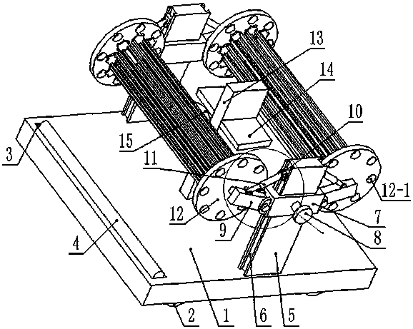
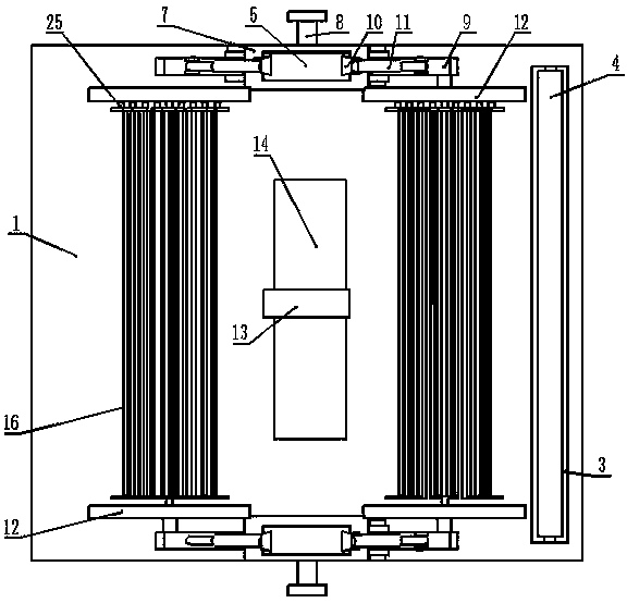
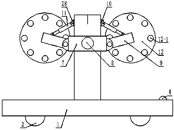
[0028] Such as Figure 1-Figure 8 As shown, a steel pipe placement frame in a machinery factory includes a base 1 and a rotating placement bracket. The rotating placement bracket includes a corresponding pair of rotating disks 12, and the rotating disks 12 are evenly provided with a number of insertion holes 12 in a circular shape. -1, between the corresponding pair of said rotating discs 12, there are several placing racks which are uniformly supported and rotated in a ring.

[0029] Preferably, the placement frame 16 includes corresponding side plates A17 and side plates B18, the side plate A17 is provided with a through hole 17-1, and a fan 27 for blowing is arranged in the through hole 17-1, One side of the side plate A17 is provided with a motor 25, and the motor 25 is fixed to the side plate A17 through a curved fixing rod 26. The shaft o...


PUM


Abstract

The invention discloses a steel tubing placement rack of a machinery plant. The steel tubing placement rack comprises a base, wherein wheels for moving are mounted at the bottom of the base, supporting upright plates are symmetrically fixed at the two sides of the upper part of the base, frame-shaped sliding blocks sleeve the supporting upright plates, supporting plate blocks are symmetrically hinged to the two sides of each frame-shaped sliding block, and a rotary-placed bracket is arranged between every two pairs of opposite-arranged supporting plate blocks. According to the steel tubing placement rack, the operation is simple, the use is convenient, the moving is relatively laborsaving, steel pipes on the rotary-placed brackets are fully wrapped together through drawing a plastic layeron a winding rod in a placement groove when the weather is poor so as to achieve a rainproof function, and thus, the protective work is relatively convenient; height positions between the frame-shapedsliding blocks and the rotary-placed brackets on the supporting upright plates and the bottom surface are adjusted through unscrewing locking screws A, global positions of the rotary-placed bracketscan be raised, thus, moist air flow of the ground can be prevented from being in contact with the steel pipes, the steel pipes can be prevented from long-time wetted rusting, the steel pipes are prevented from rusting, and the quality of the steel pipes is ensured.

Description

technical field [0001] The invention relates to the field of steel pipes, in particular to a steel pipe display rack for a machinery factory. Background technique [0002] With the continuous expansion of industrial production scale, the demand for steel pipes is increasing, especially for precision special steels, which are widely used in important occasions such as aerospace, oil, natural gas, etc., which will involve the storage of steel pipes, traditional storage They all use simple wood as a support to stack the steel pipes directly on top, which is prone to moisture and rust for a long time, which affects the quality of the steel pipes; impurities easily enter the inside of the steel pipes during storage, which affects the use of the steel pipes. When the steel pipe is placed on the ground from the shelf, it needs to use a lifting machine, which is very troublesome and economical. In rainy days, it is necessary to prepare additional plastic to cover the steel pipe, and...

Claims


Application Information

Patent Timeline
Patent Type & Authority Applications(China)
IPC IPC(8): B25H3/04B08B5/02
CPCB25H3/04B08B5/02
Inventor 郭良山
Owner DONGGUAN KAILEDI NUMERICAL CONTROL SCI & TECH CO LTD
Why Eureka
Try Eureka