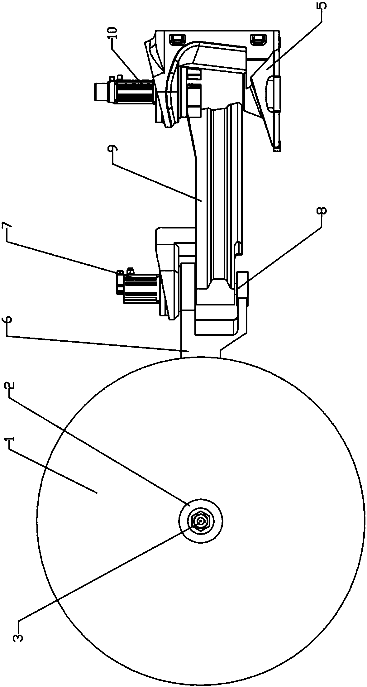
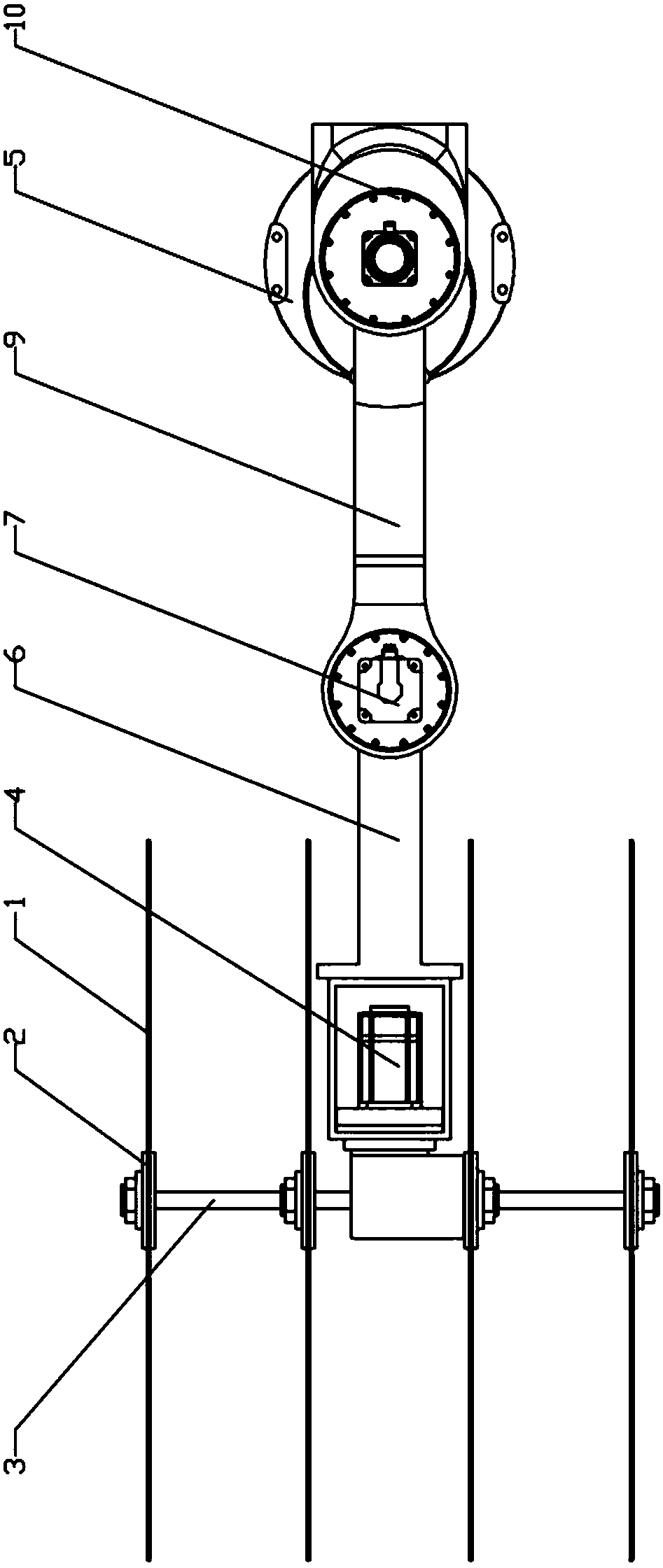
Cutting device for digging robot

A technology of cutting device and robot, which is applied in the direction of manipulators, program-controlled manipulators, mining equipment, etc., can solve the problems of high cost, time-consuming and labor-consuming, and affecting the construction period of shield machines, and achieve low cost, improve the scope of work, and ensure cutting efficiency effect

Inactive Publication Date: 2018-06-08
CHONGQING PENG TECH
View PDF4 Cites 4 Cited by
  • Summary
  • Abstract
  • Description
  • Claims
  • Application Information

AI Technical Summary

Problems solved by technology

[0004] The first is that workers hold conventional drilling tools, such as rhinestones or barrel drills, to drill a section of rock and then take it out, and continue to drill the next section. This method is time-consuming and labor-intensive in the process. A 3m*3m square hole, Two workers can only d

Method used


Image

  • Cutting device for digging robot
  • Cutting device for digging robot

Examples


Embodiment Construction

[0020] Further detailed explanation through specific implementation mode below:

[0021] The technical solutions of the present invention will be clearly and completely described below in conjunction with the accompanying drawings. Apparently, the described embodiments are some of the embodiments of the present invention, but not all of them. Based on the embodiments of the present invention, all other embodiments obtained by persons of ordinary skill in the art without making creative efforts belong to the protection scope of the present invention.

[0022] In the description of the present invention, it should be noted that the terms "center", "upper", "lower", "left", "right", "vertical", "horizontal", "inner", "outer" etc. The indicated orientation or positional relationship is based on the orientation or positional relationship shown in the drawings, and is only for the convenience of describing the present invention and simplifying the description, rather than indicating...


PUM


Abstract

The invention discloses a cutting device for a digging robot. The device comprises a mechanical arm and a cutting machine which is driven by the mechanical arm to move in the space; the mechanical armcomprises a machine base, an inner arm which is rotatably connected to the machine base at the single degree of freedom in the vertical direction, an outer arm which is rotatably connected to the inner arm at the single degree of freedom in the vertical direction, a first driving device for driving the outer arm to rotate relative to the inner arm and a second driving device for driving the innerarm to rotate relative to the machine base. Therefore, the mechanical arm with high length and weight can be adopted for the cutting device for the digging robot, the bending moment generated under the gravity of the mechanical arm is prevented from damaging the driving devices (usually gear motors), and accordingly the operation range of the cutting device for the digging robot is greatly enlarged.

Description

technical field [0001] The invention relates to the field of cutting, in particular to a cutting device for an excavating robot. Background technique [0002] The pipe corridor (called "common ditch" in Japan and "common pipeline" in Taiwan) is a comprehensive corridor of underground urban pipelines. That is to build a tunnel space underground in the city, integrating various engineering pipelines such as power, communication, gas, heating, water supply and drainage, etc., with special inspection ports, hoisting ports and monitoring systems, implementing unified planning, unified design, Unified construction and management is an important infrastructure and "lifeline" to ensure the operation of the city. It is generally "open" type, the main place for centralized laying of large-scale installation pipelines, it is composed of columns, beams and trusses of steel structure or reinforced concrete structure, and can be divided into single-layer or multi-layer according to the t...

Claims


Application Information

Patent Timeline
IPC IPC(8): B25J9/02B25J11/00B25J19/00E21D9/10
CPCB25J9/02B25J11/00B25J19/00E21D9/1006
Inventor 王盛学
Owner CHONGQING PENG TECH
Why Eureka
Try Eureka