
Plug for automobile fuel pump

A fuel pump and plug technology, which is applied to liquid fuel feeders, engine components, machines/engines, etc., can solve problems such as poor isolation effect, and achieve comprehensive protection and tight coordination.

Active Publication Date: 2018-06-08
重庆安布伦斯科技有限公司
View PDF6 Cites 2 Cited by
  • Summary
  • Abstract
  • Description
  • Claims
  • Application Information

AI Technical Summary

Problems solved by technology

[0004] The prior art has the following technical problems: since the fuel pump is arranged in the fuel tank, the plug of the fuel pump is soaked by the fuel for a long time, and a small amount of fuel will be immersed through the gap between the annular protrusion 5 and the annular groove 42; Ineffective

Method used


Image

  • Plug for automobile fuel pump
  • Plug for automobile fuel pump
  • Plug for automobile fuel pump

Examples


Embodiment 1

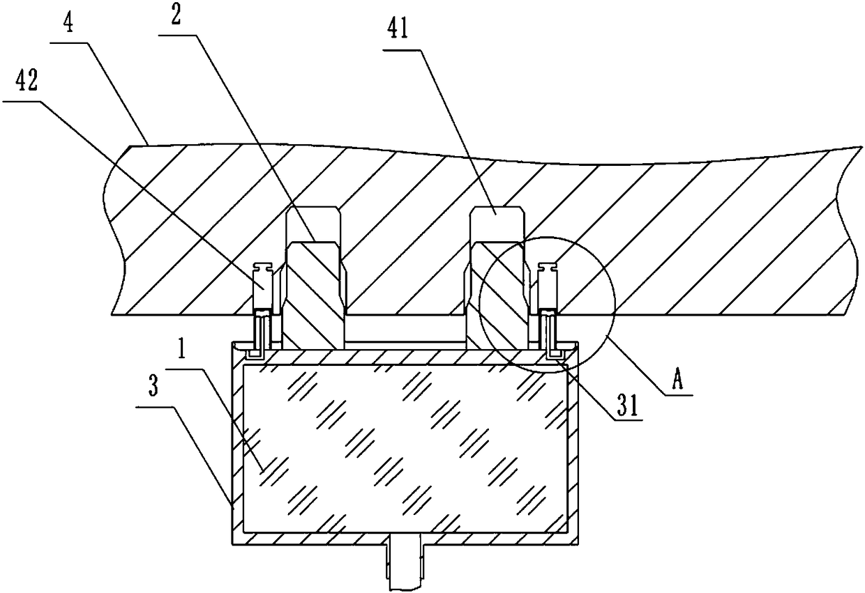
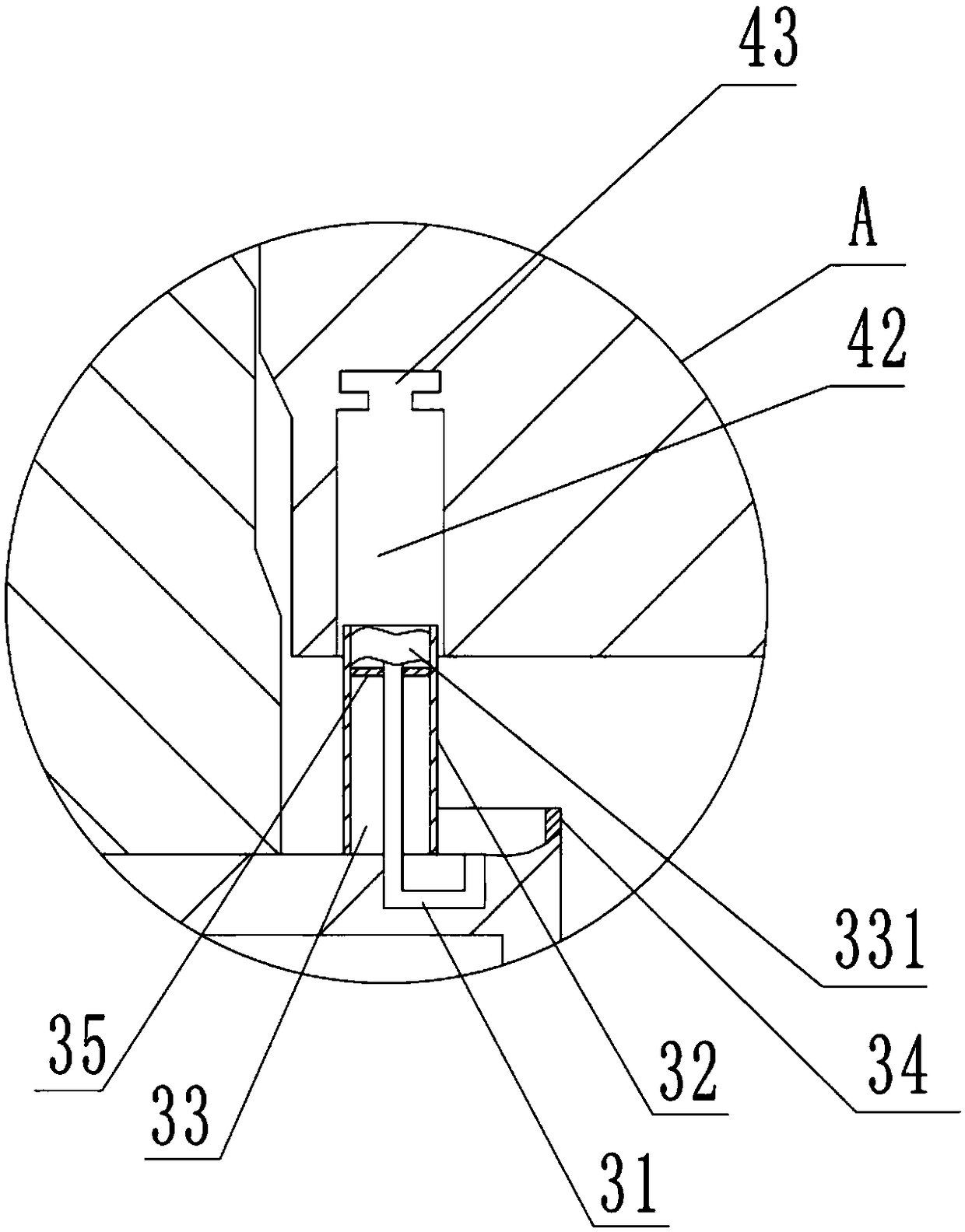
[0025] A plug for an automobile fuel pump, including a plug body 1 and pins 2 located on the plug body 1; also includes an anti-corrosion layer 3 wrapped on the outer surface of the plug body 1, and the pins 2 pass through the anti-corrosion layer 3; anti-corrosion A fuel pipe 31 for fuel oil entry is provided in the layer; an isolating ring 32 is fixed on the anti-corrosion layer 3, and the isolating ring 32 is located in the circumferential direction of the pin 2; an annular groove 33 is arranged in the isolating ring 32; There is a circle of annular air bag 331, and the annular air bag 331 communicates with the fuel pipe 31;

[0026] A rubber ring 34 is also fixed on the edge of the upper surface of the anti-corrosion layer 3 , and the inlet of the fuel pipe 31 is located between the rubber ring 34 and the spacer ring 32 .

[0027] The surface between the rubber ring 34 and the inlet of the fuel pipe 31 is a slope inclined downward toward the inlet of the fuel pipe 31 . Th...

Embodiment 2

[0031] The difference between this embodiment and embodiment 1 is that the anti-corrosion layer 3 is a titanium alloy layer.

[0032] When in use, the pin 2 is inserted into the socket hole 41 ; the isolation ring 32 is inserted into the annular groove 42 . The rubber ring 34 bears against the surface of the socket 4 . Fuel oil can be stopped by rubber ring 34 earlier, can not contact with pin 2. When the rubber ring 34 is damaged, the fuel will enter the fuel pipe 31 and enter the airbag through the fuel pipe 31. After the airbag gradually expands, it will be in close contact with the inner bottom surface of the annular groove 42, thereby preventing the fuel from entering the isolation ring. 32 and the contact surface of the annular groove 42. In addition, if the airbag continues to expand, it will enter the fixing groove 43 on the inner bottom of the annular groove 42; since the cross section of the fixing groove 43 is T-shaped, the airbag will snap into the fixing groove ...


PUM


Abstract

The invention relates to the technical field of automobile parts, in particular to a plug for an automobile fuel pump. The plug for the automobile fuel pump comprises a plug body and a plug pins located at the plug body; the plug for the automobile fuel pump further comprises an anti-corrosive layer covering the outer surface of the plug body, and the plug pins pass through the anti-corrosive layer; fuel pipes for fuel oil entry are arranged in the anti-corrosive layer; the anti-corrosive layer is fixedly provided with a round of isolating rings, and the isolating rings are located at the circumference of the plug pins; annular grooves are arranged in the isolating rings; a round of annular air bags are arranged in each annular groove, and the annular air bags communicate with the fuel pipes; and the annular air bags are located at one sides away from the anti-corrosive layer. The plug for the automobile fuel pump can ensure that the fuel oil can not contact the pins.

Description

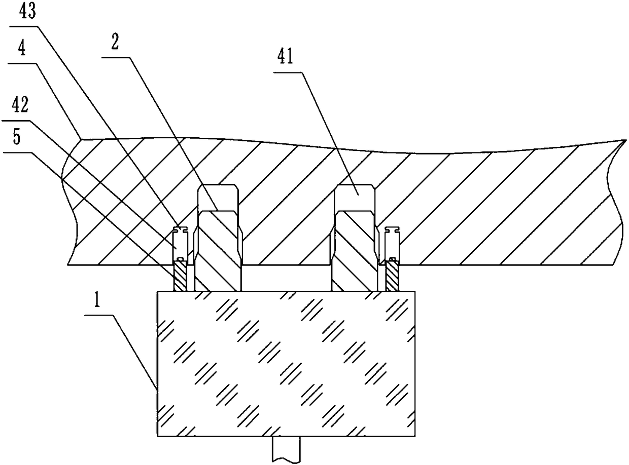
technical field [0001] The invention relates to the technical field of auto parts, in particular to a plug for an auto fuel pump. Background technique [0002] The fuel pump is generally set in the fuel tank of the car, and is used to deliver fuel from the fuel tank to the internal combustion engine. Known fuel pumps have one or two pump stages, which are driven by an electric motor. Since the fuel pump is arranged in the fuel tank, the plug of the fuel pump is also soaked by fuel. Fuel, on the other hand, is a corrosive substance that corrodes the connection points of the plugs. In particular if the fuel contains methanol or ethanol, the connection point is corroded in such a way that it is permanently damaged and this leads to failure of the fuel pump. [0003] In order to solve the above problems, such as figure 1 As shown, the fuel pump plug in the prior art includes a plug body 1 and a pin 2 located on the plug body 1 ; a circle of annular protrusions 5 is provided ...

Claims


Application Information

Patent Timeline
Patent Type & Authority Applications(China)
IPC IPC(8): F02M37/10
CPCF02M37/0011F02M37/103
Inventor 彭洪德曹建国
Owner 重庆安布伦斯科技有限公司
Learn More