

Bearing and cage thereof
A technology for cages and bearings, applied to bearing components, shafts and bearings, mechanical equipment, etc., can solve problems such as easy wear and poor lubrication environment, and achieve the effect of improving the lubrication environment
- Summary
- Abstract
- Description
- Claims
- Application Information
AI Technical Summary
Problems solved by technology
Method used
Image

Examples
no. 1 example
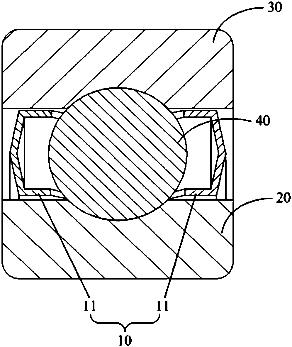
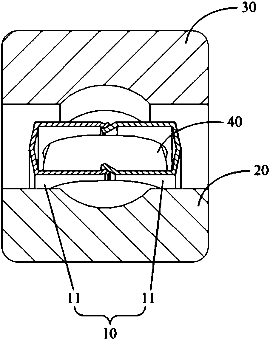
[0030] refer to figure 1 , figure 2 As shown, this embodiment provides a bearing and its cage 10, wherein the bearing includes an inner ring 20 and an outer ring 30 sleeved coaxially, and the cage 10 is coaxially arranged on the inner ring 20 and the outer ring 30 Between, for supporting the roller 40.
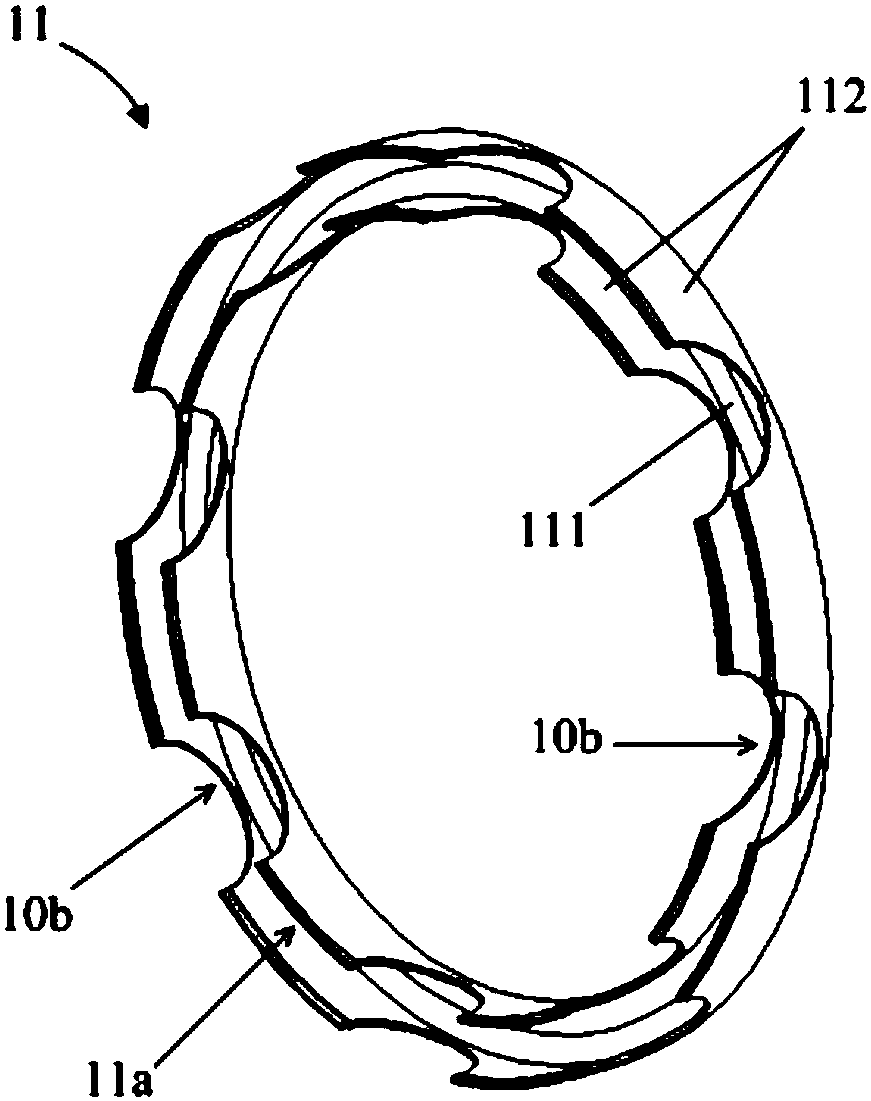
[0031] to combine image 3 As shown, the cage 10 includes coaxial and face-to-face support rings 11, the support ring 11 is coaxially provided with an annular groove 11a, the opening of the annular groove 11a faces the other support ring 11 in the axial direction, and the two support rings 11 The openings of the middle annular groove 11a are arranged face to face. The annular groove 11a can be used to accommodate and store lubricant.
[0032] The support ring 11 includes a bottom 111 for forming the bottom wall of the annular groove 11a, and side portions 112 respectively located on both radial sides of the bottom 111 to form the side walls of the annular groove 11a. The...
no. 2 example
[0047] The difference between this embodiment and the first embodiment is that the shape of the connecting portion of the support rings 11 is different, so the connection manner between the two support rings 11 is different.
[0048] In this example, if Figure 6 , Figure 7 As shown, the connecting portion is a connecting flange surface 10d provided at the free end of the side portion 112, wherein the connecting flange surface 10d is located between two adjacent pockets 10b. The two supporting rings 11 are connected to each other through the connecting flange surface 10d. A connecting flange surface 10d may be provided between any two adjacent pockets 10b.
[0049] Wherein, in each supporting ring 11, the connecting flange surface 10d may be located on the opposite side of the side and the other side, or on the side opposite to each other. Such as Figure 6 , Figure 7 , in order to facilitate processing and installation, the connecting flange surface 10d extends from th...
no. 3 example
[0052] In this embodiment, a sealing structure is added on the basis of the first embodiment or the second embodiment.
[0053] refer to Figure 8 As shown, one end of the support ring 11 facing away from the other support ring 11 in the axial direction is provided with a first annular flange 113 protruding radially outward and a second annular flange 114 protruding radially inward. From Figure 8 It can be seen from the schematic cross-sectional view shown in the assembled state that the axially outer end of each support ring 11 (that is, the end facing the outside of the bearing in the axial direction) is provided with a first annular flange 113 and a second annular flange 113 . flange 114 .
[0054] Correspondingly, a first annular groove 31 facing the first annular flange 113 is provided on the inner peripheral surface of the outer ring 30 of the bearing, and the first annular flange 113 is accommodated in the first annular groove 31; the inner ring 20 A second annular ...
PUM
 Abstract
Description
Claims
Application Information