Hydraulic unit

A hydraulic assembly and assembly technology, applied in the field of hydraulic assembly, can solve problems such as unfavorable functions, and achieve the effect of simple control, lifting parts and assembly costs

Active Publication Date: 2018-06-08
ROBERT BOSCH GMBH
View PDF8 Cites 0 Cited by
  • Summary
  • Abstract
  • Description
  • Claims
  • Application Information

AI Technical Summary

Problems solved by technology

[0005] If a damping device is now connected to the thus extended fluid channel for damping pressure pulses, this has the disadvantage that the throttle element connected downstream of the pressure medium accumulator is a flow resistance, which is disadvantageous in the operating state of the vehicle brake system In this operating state, it is important to provide the largest possible pressure medium volume as quickly as possible

Method used


Image

  • Hydraulic unit
  • Hydraulic unit
  • Hydraulic unit

Examples


Embodiment Construction

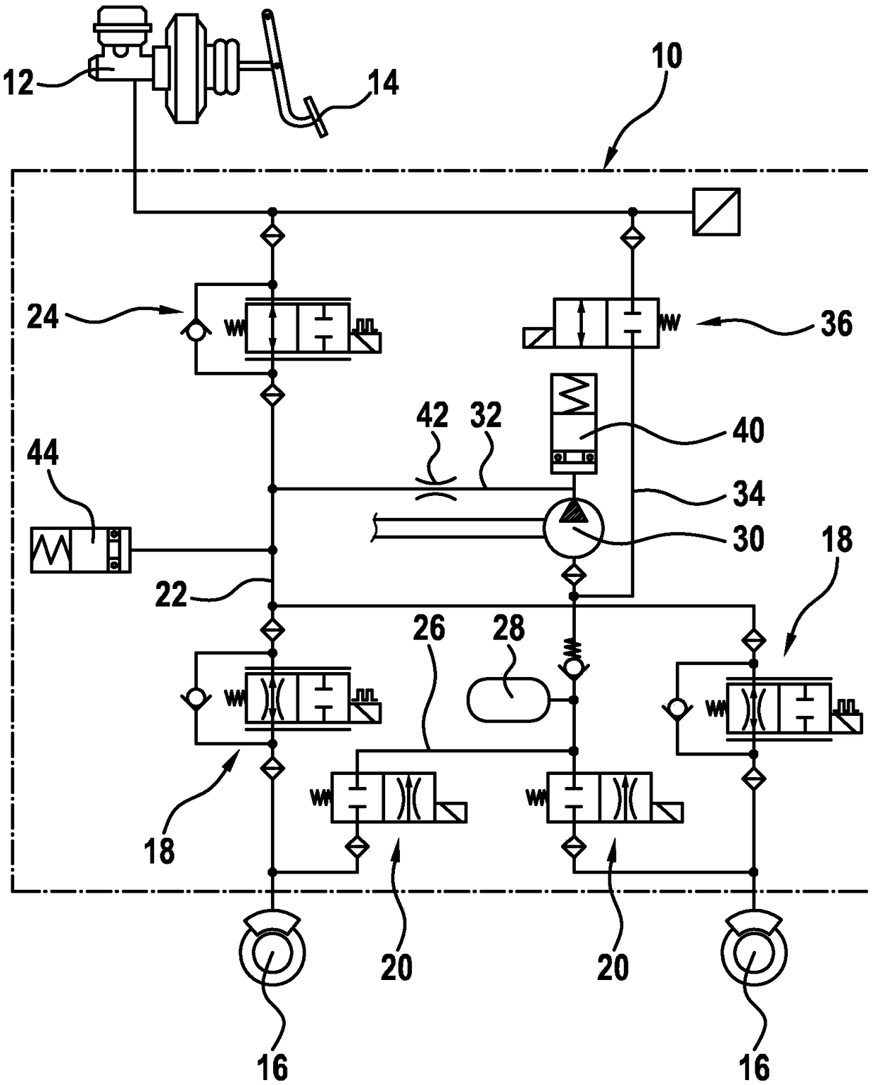
[0021] figure 1 The hydraulic components of a brake circuit of a vehicle brake system are shown with the aid of a hydraulic circuit diagram. The hydraulic components are partly coupled indirectly to the hydraulic unit 10 or partly arranged directly on the hydraulic unit 10 . The hydraulic assembly 10 itself is in the figure 1 is shown symbolically. Coupled to the hydraulic unit 10 is a master brake cylinder 12 which can be actuated by the driver via a brake pedal 14 . Furthermore, for example two wheel brakes 16 are coupled to hydraulic unit 10 , which are supplied with pressure medium from hydraulic unit 10 . In order to control the brake pressure depending on the immediate slip situation at the wheels of the vehicle assigned to the wheel brakes 16 , a so-called boost valve or inlet valve 18 and a so-called pressure-reducing valve or outlet valve 20 are assigned to each wheel brake 16 . Inlet valve 18 is located in pressure medium connection 22 , which connects the conne...


PUM


Abstract

The invention relates to a hydraulic unit (10), in particular for a slip-controllable vehicle brake system, comprising a housing block (52) and a pump (30) held in a pump receptacle (50) of the housing block (52), said pump having a pump intake side and a pump delivery side. A first fluid duct (80) intersects the pump receptacle (50) in the region of the pump delivery side. In addition to the first fluid duct (80), the invention proposes the provision of a second fluid duct (82) in the housing block (52), said second fluid duct opening into the pump receptacle (50) in the region of the pump delivery side, and additionally the provision of a first separation point (100) which seals off the two fluid ducts (80, 82) from one another. The invention allows contact with a damping device (44) which damps pulsations and reduces the operating noise of the hydraulic unit (10) without having a detrimental effect on the functional characteristics, in particular on the pressure build-up dynamics ofthe vehicle brake system, or without jeopardising the compact construction of the hydraulic unit (10).

Description

technical field [0001] The invention relates to a hydraulic assembly according to the features of the preamble of claim 1 , in particular for an antiskid controllable vehicle brake system. Background technique [0002] Such a hydraulic assembly is known, for example, from DE 10 2008 002 740 A1. This known hydraulic assembly has a housing block on which the individual parts for adjusting the brake pressure depending on the existing wheel slip are arranged and are in hydraulic contact with one another. The essential part for this is the pump, which is installed in the pump receptacle of the housing block and is actuated, for example mechanically, by means of an electric motor and an eccentric driven by the electric motor. The pump delivers pressure medium away from the wheel brakes when required to reduce the wheel brake pressure, or supplies pressure medium at high pressure to the wheel brakes as soon as the wheel brake pressure needs to be increased. [0003] Pumps, in par...

Claims


Application Information

Patent Timeline
Patent Type & Authority Applications(China)
IPC IPC(8): B60T8/40
CPCB60T8/368B60T8/4031B60T8/4068F04B1/0404F04B1/0421F04B53/16B60Y2400/81B60T13/16B60T13/161B60T2270/203F15B21/008
Inventor B·霍伊瑟尔O·加尔特纳W·迈莱恩德R·斯托兹O·亨尼格M·舒斯勒
Owner ROBERT BOSCH GMBH
Why Eureka
Try Eureka