A Multifunctional Swing Blade Type Multi-pressure Output Rotary Mechanical Mechanism

A rotating machinery and vane-type technology, which is applied in the field of variable-displacement swing-vane hydraulic rotary devices, can solve problems such as unfavorable system safety and stable operation, inability to realize pressure output, transmission noise and wear, and achieve enhanced oil supply continuity , Reduce the effect of reducing flow noise between parts

Active Publication Date: 2018-08-07
SUZHOU HE ER BAI SI PUMP CO LTD
View PDF7 Cites 0 Cited by
  • Summary
  • Abstract
  • Description
  • Claims
  • Application Information

AI Technical Summary

Problems solved by technology

[0005] Solution 1: The contact surface between the pendulum plate 3 and the pendulum plate groove ring 2 is a hard surface contact, and the vibration shock transmitted to the pendulum plate 3 by the high pressure of the liquid in the cavity 7 of the B series during the compression process is relatively large , and there is no force to balance it, so the transmission noise and wear problems of the hard surface contact are particularly prominent
[0006] Insufficient solution 2: There is a clearance fit between the fixed seat 1 and the slot ring 2 of the swing plate, and the lubrication is realized through the oil film. While the oil film plays a role in lubrication, at low temperature due to the high viscosity of the oil, there is a gap between the two. The continuous viscous resistance acts on the entire annulus. The viscous loss caused by such a large rotating contact area is very large, which increases the friction loss work of the entire mechanism. Generate instantaneous high-voltage shock, which is not conducive to the safe and stable operation of the system
[0007] Insufficient solution 3: The mechanism can only form two pressure outputs of different sizes in the A series cavity 6 and the B series cavity 7, and cannot realize the pressure output of more requirements, and the A series cavity 6 is divided by the swing plate 3 Will form a regular pressure pulsation, also prone to noise problems

Method used


Image

  • A Multifunctional Swing Blade Type Multi-pressure Output Rotary Mechanical Mechanism
  • A Multifunctional Swing Blade Type Multi-pressure Output Rotary Mechanical Mechanism
  • A Multifunctional Swing Blade Type Multi-pressure Output Rotary Mechanical Mechanism

Examples


Embodiment

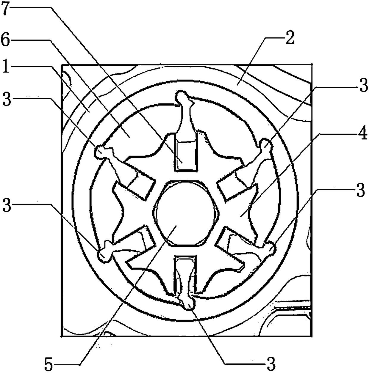
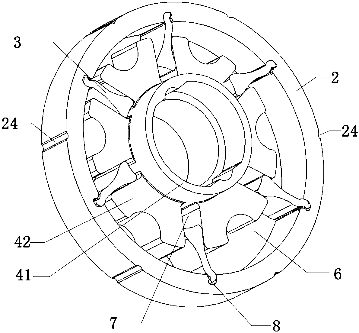
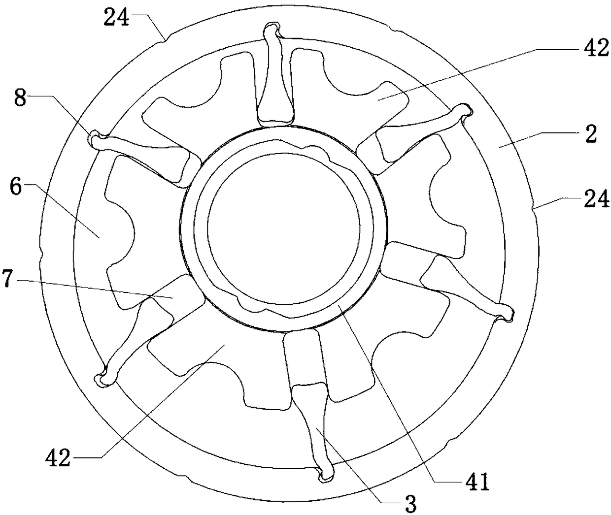
[0044] A multi-functional swing blade type multi-pressure output rotary mechanical mechanism, which is fixed on the bracket 1 through the eccentric shaft 5, such as Figure 2-3 As shown, the multi-function swing vane type multi-pressure output rotary mechanical mechanism includes a swing plate slotted ring 2 , a set of swing plates 3 and a serrated grooved plate 4 .

[0045] Among them, such as Figure 4-5 As shown, the swing piece 3 includes a swing piece head 31 and a swing piece foot 32 , the swing piece head 31 has a swing piece head concave portion 311 , and the swing piece foot 32 has a swing piece foot concave portion 321 . In addition, the head 31 of the pendulum piece 31 passes through the front neck 33 of the pendulum piece 3 sunken toward the middle of the pendulum piece 3 and the chest 34 of the pendulum piece protruding toward the middle of the pendulum piece 3 on the front side of the pendulum piece 3, and further extends to the foot 32 of the pendulum piece. An...


PUM


Abstract

A multifunctional rotary mechanical structure having oscillating blades and outputting multiple pressures comprises a oscillating blade retaining slot ring (2), a group of oscillating blades (3), and a serrated slot disc (4). The oscillating blade (3) comprises an oscillating blade head (31) and an oscillating blade foot (32). The oscillating blade head (31) is provided with an indented oscillating blade head portion (311). At the front side of the oscillating blade (3), the oscillating blade head (31), an oscillating blade front neck portion (33) indented towards a middle portion of the oscillating blade (3), an oscillating blade chest portion (34) protruding outwards towards the middle portion of the oscillating blade (3), and the oscillating blade foot (32) sequentially located from top to bottom form a front side balancing cam (35) of the oscillating blade. At the rear side of the oscillating blade (3), the oscillating blade head (31), an oscillating blade rear neck portion (36) protruding outwards towards the middle portion of the oscillating blade (3), and the oscillating blade foot (32) form a rear side balancing cam (37) of the oscillating blade (3). The mechanism has a reasonable structure, can effectively reduce noise caused by collision between the oscillating blades (3) and the oscillating blade retaining slot ring (2) and reduce viscous resistance between the oscillating blade retaining slot ring (2) and a fixing seat (1), and generates an extra pressured chamber output, resulting in a three-pressure pump structure outputting three different pressures simultaneously.

Description

technical field [0001] The present invention relates to industrial pump equipment, variable-displacement swing vane hydraulic rotary devices for automobile engines and gearboxes, in particular to a multifunctional swing vane multi-pressure output rotary mechanical mechanism, especially but not limited to hydraulic devices. Background technique [0002] Prior art CN1875190A proposes a swing slide valve mechanism, such as figure 1 As shown, the fixed seat 1, the slot ring 2 of the pendulum plate, the pendulum plate 3, the serrated groove plate 4, and the eccentric shaft 5 are composed of the fixed seat 1, the slotted ring 2 of the pendulum plate, and the eccentric shaft 5. Or counterclockwise circular motion. [0003] There are a plurality of slots 21 evenly distributed in the circumferential direction on the slot ring 2 of the swing piece (there are 6 slots in the figure in this example), and a swing piece 3 is arranged in each slot, and the slot ring 2 of the swing piece pe...

Claims


Application Information

Patent Timeline
Patent Type & Authority Patents(China)
IPC IPC(8): F04C2/44F16N13/20
CPCF04C2/44F16N13/20
Inventor 罗金
Owner SUZHOU HE ER BAI SI PUMP CO LTD
Why Eureka
Try Eureka