Display method, apparatus, electronic device and computer program product

A display method and a preset range technology, which are applied to static indicators, cathode ray tube indicators, instruments, etc., can solve the problem that the field of view has a large impact, cannot assist low-vision patients with the distance of objects, and cannot make good use of user residuals. vision problems

Active Publication Date: 2021-09-17
CLOUDMINDS SHANGHAI ROBOTICS CO LTD
View PDF5 Cites 0 Cited by
  • Summary
  • Abstract
  • Description
  • Claims
  • Application Information

AI Technical Summary

Problems solved by technology

[0005] Existing vision aids usually have a great impact on the user's field of vision, cannot make better use of the user's residual vision, and cannot assist low-vision patients to effectively perceive the distance of objects in the environment through images

Method used


Image

  • Display method, apparatus, electronic device and computer program product
  • Display method, apparatus, electronic device and computer program product
  • Display method, apparatus, electronic device and computer program product

Examples


Embodiment 1

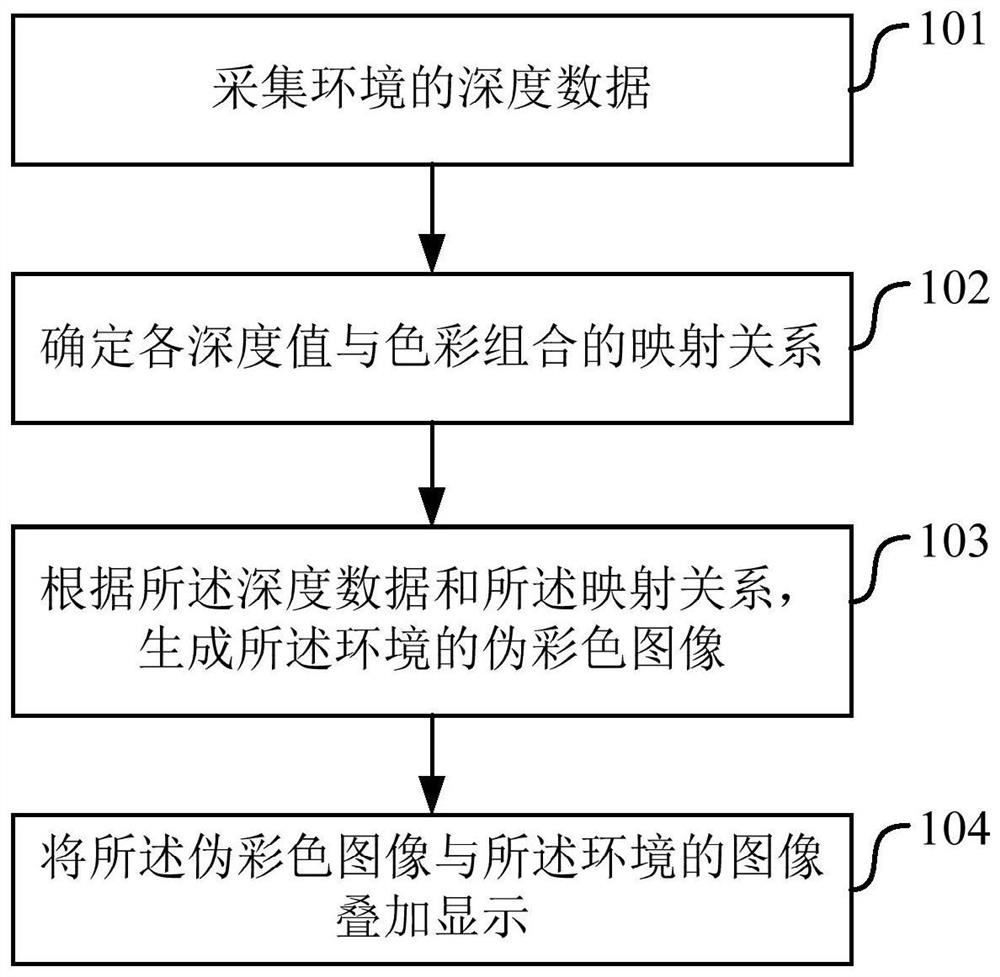
[0029] figure 1 A schematic flowchart of the display method in the first embodiment of the present application is shown, such as figure 1 As shown, the display method includes:

[0030] Step 101, collecting depth data of the environment;

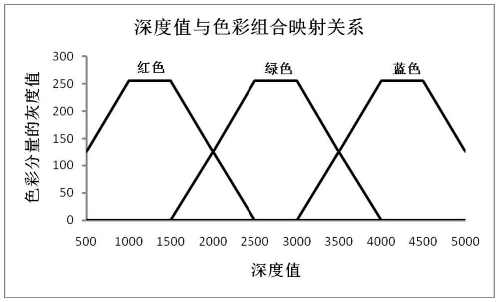
[0031] Step 102, determine the mapping relationship between each depth value and color combination;

[0032] Step 103, generating a pseudo-color image of the environment according to the depth data and the mapping relationship;

[0033] Step 104, superimposing the pseudo-color image and the image of the environment to display.

[0034] Taking AR glasses worn by patients with low vision as an example, in step 101, the AR glasses worn by patients with low vision collect depth data of the environment. The depth data here can be directly collected by the depth sensor and depth-of-field camera mounted on the AR glasses, or it can be obtained by the binocular camera mounted on the AR glasses after collecting the front environment image for cal...

Embodiment 2

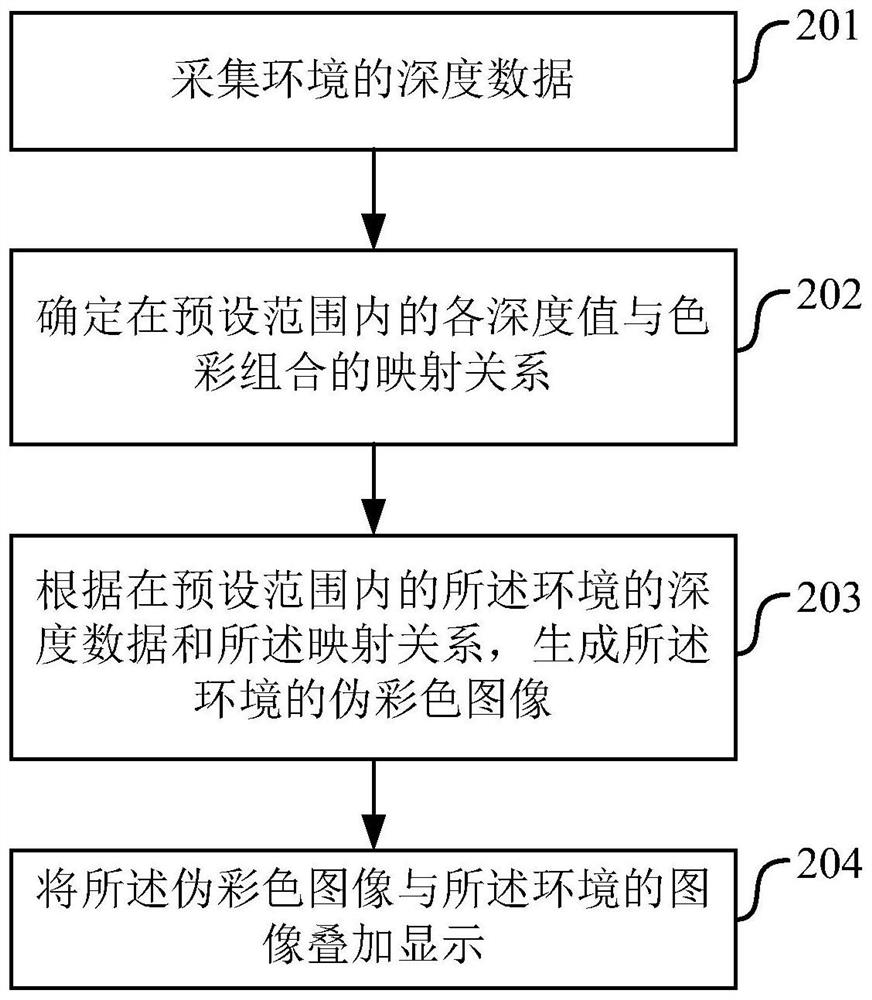
[0050] image 3 A schematic flowchart of the display method in the second embodiment of the present application is shown, such as image 3 As shown, the display method includes:

[0051] Step 201, collecting depth data of the environment;

[0052] Step 202, determining the mapping relationship between each depth value and color combination within a preset range;

[0053] Step 203, generating a pseudo-color image of the environment according to the depth data of the environment within a preset range and the mapping relationship;

[0054] Step 204, superimposing the pseudo-color image and the image of the environment to display.

[0055] For the implementation of step 201, reference may be made to the description of step 101 in the above-mentioned first embodiment. In step 201, the depth data of the environment is collected.

[0056] In step 202, a mapping relationship between each depth value and color combination within a preset range is determined, where the preset range ...

Embodiment 3

[0070] Figure 5 A schematic flowchart of the display method in the third embodiment of the present application is shown, such as Figure 5 As shown, the display method includes:

[0071] Step 301, collecting depth data of the environment; generating a grayscale image according to the depth data of the environment;

[0072] Step 302, determine the mapping relationship between each depth value and the color combination; determine the mapping relationship between each gray value and the color combination according to the mapping relationship between the each depth value and the color combination;

[0073] Step 303, generating a pseudo-color image of the environment according to the grayscale map generated by the depth data and the mapping relationship between the grayscale values ​​and color combinations;

[0074] Step 304, superimposing the pseudo-color image and the image of the environment to display.

[0075] Taking AR glasses worn by patients with low vision as an example,...


PUM


Abstract

Display method, device, electronic equipment and computer program product, the method includes: collecting depth data of the environment; determining the mapping relationship between each depth value and color combination; generating the depth data of the environment according to the depth data and the mapping relationship A pseudo-color image; displaying the pseudo-color image superimposed on the image of the environment. In this application, the depth data of the environment is mapped to obtain a pseudo-color image, and the pseudo-color image is superimposed on the current environment image for enhanced display, which can make full use of the visual field of low-vision patients without affecting the visual field of low-vision patients. Residual vision and assist it to effectively perceive the distance of objects in the environment.

Description

technical field [0001] The present application relates to the field of blind guidance technology, and in particular, to display methods, apparatuses, electronic devices and computer program products. Background technique [0002] Visual disability is a serious public health, social and economic problem worldwide. The main causes of blindness in different economic regions are different. In economically developed regions, age-related macular degeneration, diabetic retinopathy, etc. Cataracts and infectious eye diseases are predominant. Visually disabled patients are usually divided into blind and low-vision patients, of which blind people only account for about one-quarter of all visually-disabled patients, while low-vision patients account for nearly three-quarters. According to statistics, there are 40-45 million blind people and about 135 million low vision patients in the world, and about 7 million blind people and 21 million low vision patients are newly added every year...

Claims


Application Information

Patent Timeline
Patent Type & Authority Patents(China)
IPC IPC(8): G09G5/02
CPCG09G5/026
Inventor 崔华坤王恺廉士国
Owner CLOUDMINDS SHANGHAI ROBOTICS CO LTD
Why Eureka
Try Eureka