coil device
A coil device and coil layer technology, applied in the direction of coils, circuit devices, transformers/inductor coils/windings/connections, etc., can solve problems such as power efficiency decline, and achieve the effect of suppressing the generation of Joule heat
- Summary
- Abstract
- Description
- Claims
- Application Information
AI Technical Summary
Problems solved by technology
Method used
Image

Examples
no. 1 approach 〕
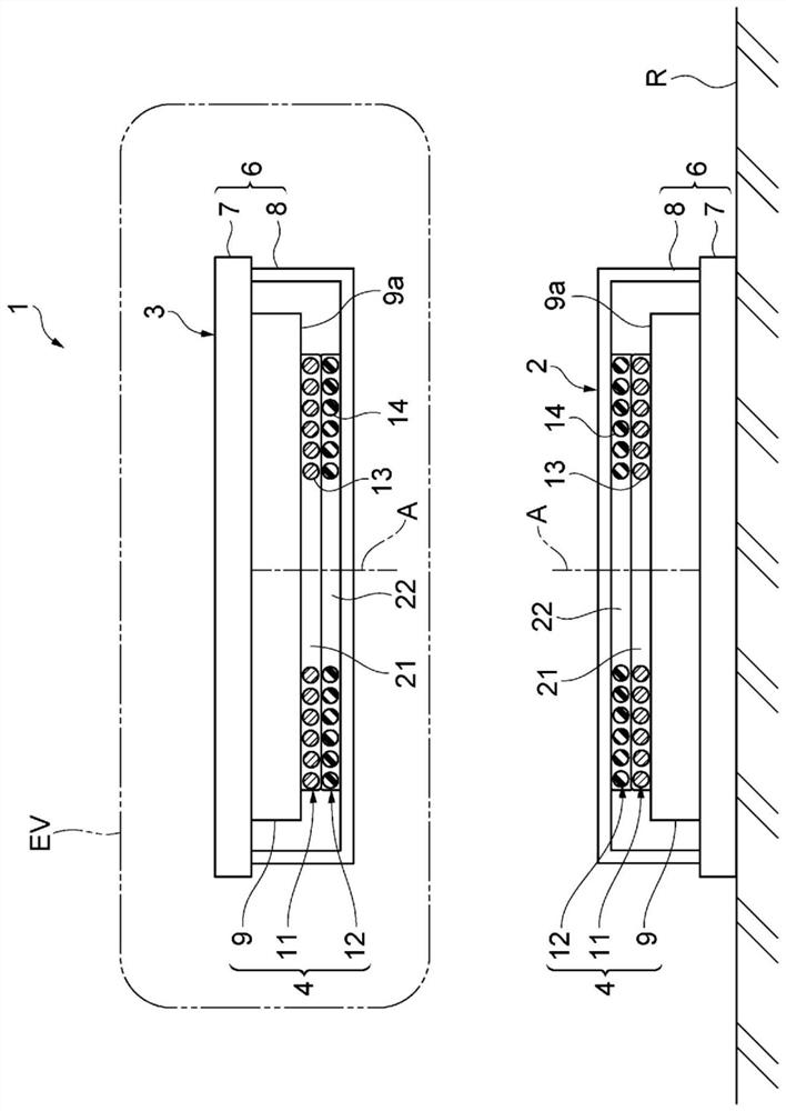
[0031] The power transmission coil device according to the first embodiment and a non-contact power supply system including the power transmission coil device will be described. like figure 1 As shown, the non-contact power supply system 1 includes a power transmission coil device 2 and a power reception coil device 3 . The non-contact power supply system 1 supplies electric power from the power transmission coil device 2 to the power reception coil device 3 in a non-contact manner. The power transmitting coil device 2 and the power receiving coil device 3 are arranged so as to be separated from each other in the up-down direction (opposing direction). The power transmission coil device 2 is installed on a road surface R such as a parking lot, for example. The power receiving coil device 3 is mounted on, for example, an electric vehicle (mobile body) EV. The non-contact power supply system 1 is configured to supply electric power to an electric vehicle EV arriving at a park...
no. 2 approach 〕
[0071] Next, the power transmission coil device 2 of the second embodiment will be described.
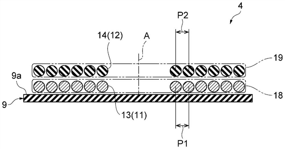
[0072] In the description of the first embodiment, when calculating the total inductance (LD), it is assumed that the first inductance ( L1 ) of the first helical coil 11 is equal to the second inductance ( L2 ) of the second helical coil. However, even when the first helical coil 11 and the second helical coil 12 have the same physical structure and electrical structure, the first inductance ( L1 ) and the second inductance ( L2 ) may not be exactly the same. For example, it is a case where the first helical coil 11 and the second helical coil 12 are arranged on the ferrite plate 9 . The ferrite plate 9 is magnetized in the magnetic field. Therefore, the magnetic flux from the ferrite plate 9 affects the inductance of the first helical coil 11 and the second helical coil 12 . In addition, the distance from the ferrite plate 9 to the first helical coil 11 is different from the dis...
Deformed example 1
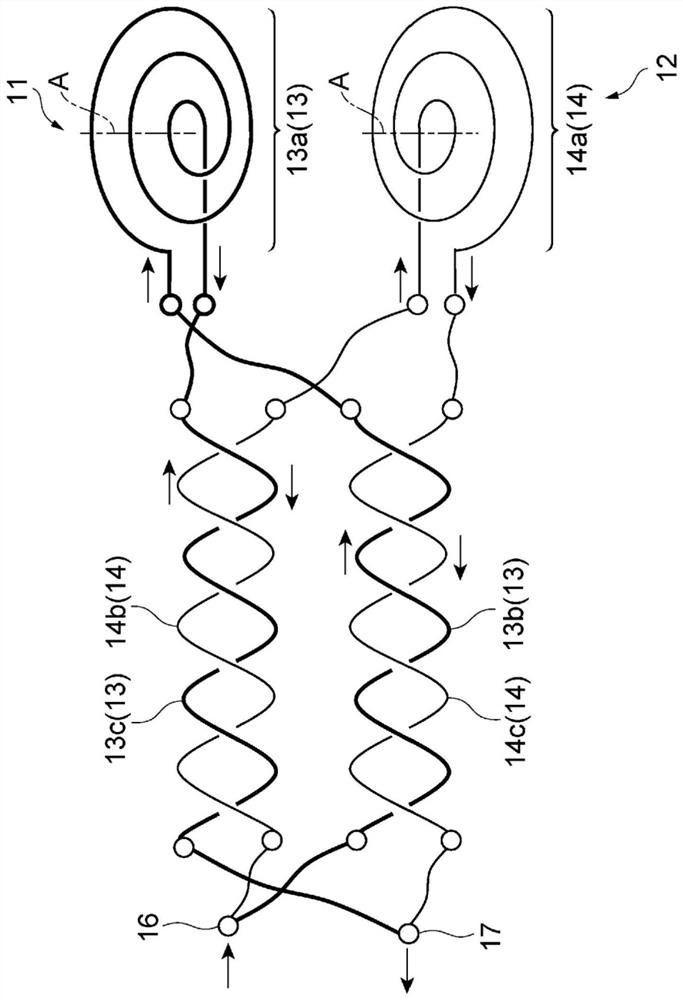
[0086] For example, as Figure 7 As shown in part (a) of , the power transmission coil device 2B of Modification 1 includes a power transmission coil unit 4B. In the power transmission coil portion 4B, the first lead wire 13B and the second lead wire 14B may be connected from the spiral portions 13a and 14a (see figure 2 ) are alternately arranged every other turn toward the outside (in the direction intersecting the axis A). That is, the first wire 13B and the second wire 14B alternate the first coil layers 18 and the second coil layers 19 at every turn. According to this configuration, the average distance difference (ΔE) between the average distance (E1) of the first helical coil 11B and the average distance (E2) of the second helical coil 12B can be further reduced.
PUM
 Abstract
Description
Claims
Application Information
 - R&D
- Intellectual Property
- Life Sciences
- Materials
- Tech Scout
- Unparalleled Data Quality
- Higher Quality Content
- 60% Fewer Hallucinations
Browse by: Latest US Patents, China's latest patents, Technical Efficacy Thesaurus, Application Domain, Technology Topic, Popular Technical Reports.
© 2025 PatSnap. All rights reserved.Legal|Privacy policy|Modern Slavery Act Transparency Statement|Sitemap|About US| Contact US: help@patsnap.com