Pit toilet flushing method and system

A technology of toilets and urinals, which is applied in flushing toilets, household utensils, buildings, etc., and can solve problems such as moving pistons and being prone to freezing

Active Publication Date: 2018-06-12
BEIJING KANGZHIWEI SCI & TECH
View PDF15 Cites 6 Cited by
  • Summary
  • Abstract
  • Description
  • Claims
  • Application Information

AI Technical Summary

Problems solved by technology

[0002] In the design scheme of Chinese patent ZL201220098457.7, there are problems that the piston is sticky and needs t

Method used


Image

  • Pit toilet flushing method and system
  • Pit toilet flushing method and system
  • Pit toilet flushing method and system

Examples


Embodiment 2

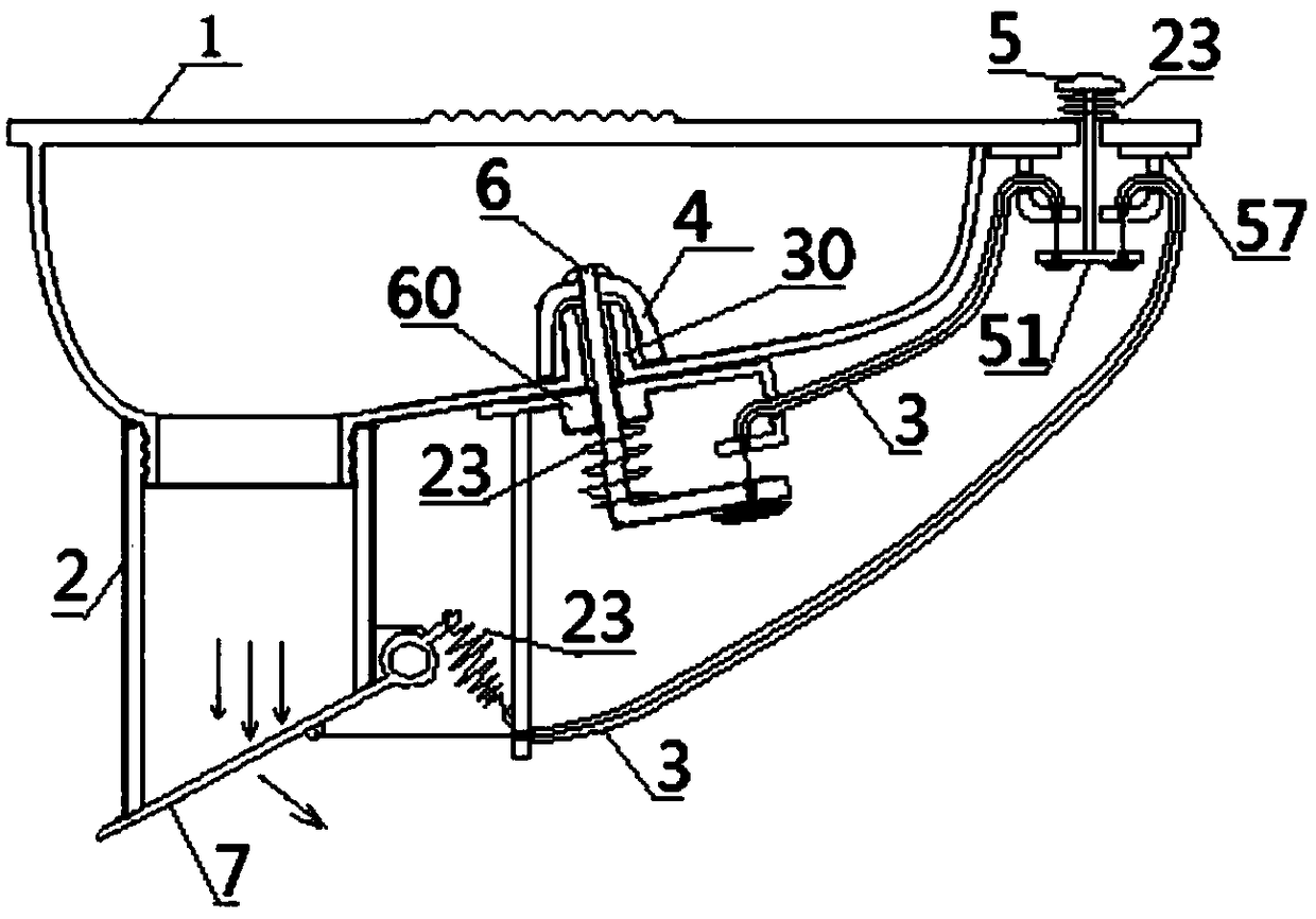
[0091] Embodiment two, such as image 3 As shown, the difference between the flushing method and system of the dry toilet of the present invention and the first embodiment is that the lower end of the discharge pipe 2 is hinged with a sealing flap 7 equipped with a return spring. The lower end of the discharge pipe 2 is an oblique opening, and the outer edge of the upper end of the oblique opening at the lower end of the discharge pipe 2 is fixed with a hinged seat. A tensile return spring 23 is fixedly connected between the extension part and the bracket fixed under the slope of the slope flow bottom groove at the front part or other fixed parts. The lower end, the plugging flap 7 are fixedly connected to the core wire lower end of the odor-proof control casing gate line 3. The blocking flap 7 is connected with the lifting pedal 5 through a push-pull transmission control mechanism.

Embodiment 3

[0092] Embodiment three, such as Figure 4As shown, the difference between the flushing method and system of the dry toilet of the present invention and the first embodiment is that the movable sealing of the odor barrier is that the lower part of the discharge pipe 2 is slidingly equipped with a horizontally reciprocating blocking gate 8 equipped with a return spring 23 . The urine delay discharge gate is provided with a hinged seat 61 through a vertical through hole, and the hinged seat 61 is hinged to a vertically inclined oblique rod 66 through a horizontal axis. The overturning dam 40 for the temporary liquid level of urine, at least the lower edge and both side edges of the overturning dam 40 are soft resin sealing edges, and the soft resin sealing sleeve 44 is sealed and connected between the vertical through hole and the oblique rod; The lower end of the inclined rod 66 is connected with the lifting pedal 5 through a push-pull transmission control mechanism. Urinary d...

Embodiment 4

[0093] Embodiment four, such as Figure 5 As shown, the difference between the flushing method and system of the dry type toilet of the present invention and the first embodiment is that the upper end surface of the ground box provided under the ground where the toilet is installed is formed with a vertical through hole, and the vertical through hole is vertically slidable on the upper end. L-shaped vertical shaft 59 with pedal 5, back-moving spring 23 (or return extension spring) is sleeved between the vertical through hole peripheral wall and the upper end (or lower end) of the T-shaped vertical shaft, and the backguy 31 connected to the lower end of L-shaped vertical shaft 59 The front end bypasses the fixed pulley 88 backwards and is extended to connect the middle part of the active horizontally long splint 20, which is fixedly connected horizontally and slidingly fitted with the horizontal push shaft 85 passing through the wall of the discharge pipe 2, and is arranged betw...


PUM


Abstract

The invention relates to a pit toilet flushing method and system so as to solve the problem that an existing pit toilet freezes easily. A bad-odor-isolating movable stopper is used for isolating bad order for a discharging pipe at the bottom and/or below a pit, and a urine delay discharging gate which is closed first to temporarily store urine and opened then to flush away excrement with the urineis arranged in the middle of a bottom groove of a pit body; under the discharging condition, a lifting pedal which is stepped down opens the bad-odor-isolating movable stopper and the urine delay discharging gate by synchronous driving, and under the non-discharging condition, the released lifting pedal releases the bad-odor-isolating movable stopper and the urine delay discharging gate synchronously so that the bad-odor-isolating movable stopper can close the discharging pipe and the urine delay discharging gate can close a urine discharging channel. The lifting pedal drives the bad-odor-isolating movable stopper and the urine delay discharging gate to be opened through a connecting rod and/or a sleeve gate wire or a fixed pulley and a pull wire wound around the fixed pulley. The pit toilet flushing method and system have the advantages that no flushing is needed or only slight flushing is needed, freezing does not occur easily, and the bad odor isolating function is good.

Description

technical field [0001] The invention relates to a dry toilet, in particular to a flushing method and system for a dry toilet. Background technique [0002] In the design scheme of the Chinese patent ZL201220098457.7, there are problems that the moving piston sticks to dirt and still needs to be flushed by a water pump, which is prone to freezing when used in a cold winter environment, and needs to be improved. Contents of the invention [0003] The purpose of the present invention is to overcome the above-mentioned defects of the prior art, and provide a dry toilet flushing method and system suitable for no-flush or micro-flush, and not easy to freeze. [0004] In order to achieve the above-mentioned purpose, the flushing method of the dry toilet of the present invention is that the discharge pipeline at the bottom and / or below of the toilet is blocked by an odor-proof activity to block the odor, and a temporary urine storage device is set in the middle of the bottom tank ...

Claims


Application Information

Patent Timeline
IPC IPC(8): A47K11/02E03D11/04E03D11/10E03D11/13
CPCA47K11/02E03D11/04E03D11/10E03D11/13Y02A50/30
Inventor 陈向前魏富儒
Owner BEIJING KANGZHIWEI SCI & TECH
Why Eureka
Try Eureka