Heat accumulation component and air conditioner

A technology for heat accumulators and air conditioners, applied in heat storage equipment, air conditioning systems, indirect heat exchangers, etc., can solve the problem of unstable defrosting and heating effects, fluctuating room temperature, and freezing and expansion of heat accumulators To achieve stable defrosting effect and heating effect, improve satisfaction, and even heating effect

Active Publication Date: 2017-03-29
WUHAN REFRIGERATION EQUIP OF MIDEA GROUP +1
View PDF5 Cites 6 Cited by
  • Summary
  • Abstract
  • Description
  • Claims
  • Application Information

AI Technical Summary

Problems solved by technology

[0002] The air conditioner in the related art usually uses the discharge temperature of the compressor to perform hot air defrosting. When defrosting starts, the four-way valve is reversed so that the outdoor heat exchanger releases heat, and the indoor heat exchanger absorbs heat, resulting in indoor ambient temperature. In this way, in a colder environment, the air conditioner runs the refrigeration cycle, which will cause the room temperature to be hot and cold, affecting the comfort of the user. In order to ensure the defrosting effect and the comfort of the user, an external heat storage component is usually added thermal capacity and improve system stability, but the non-concentrated heat storage material flow in the related technology is likely to cause the heat accumulator to freeze and expand, causing the heat sink to deform, affecting the heat dissipation effect, and resulting in unstable defrosting and heating effects

Method used


Image

  • Heat accumulation component and air conditioner
  • Heat accumulation component and air conditioner
  • Heat accumulation component and air conditioner

Examples


Embodiment Construction

[0041] In order to understand the above-mentioned purpose, features and advantages of the present invention more clearly, the present invention will be further described in detail below in conjunction with the accompanying drawings and specific embodiments. It should be noted that, in the case of no conflict, the embodiments of the present application and the features in the embodiments can be combined with each other.

[0042] In the following description, many specific details are set forth in order to fully understand the present invention. However, the present invention can also be implemented in other ways different from those described here. Therefore, the protection scope of the present invention is not limited by the specific details disclosed below. EXAMPLE LIMITATIONS.

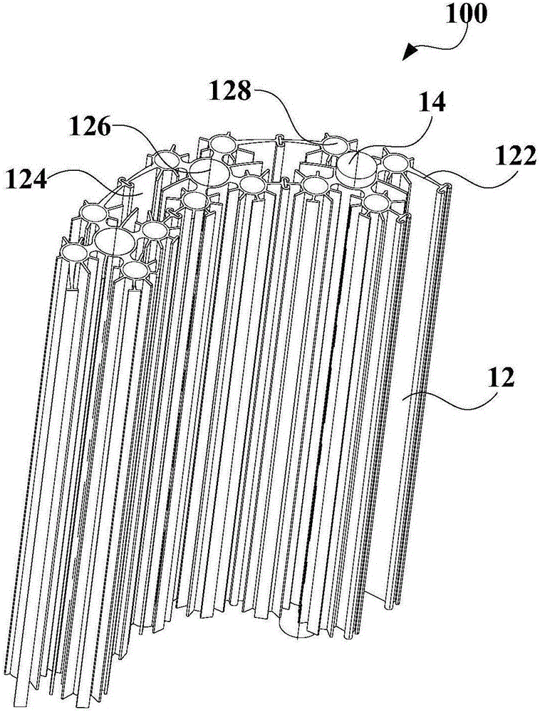
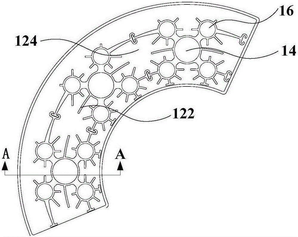
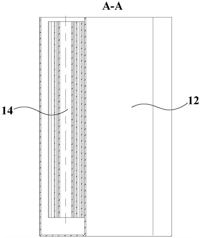
[0043] Refer below Figure 1 to Figure 3 The heat storage assembly 100 and the air conditioner according to some embodiments of the present invention are described.

[0044] Such as figure 1 , f...


PUM


Abstract

The invention provides a heat accumulation component and an air conditioner. The heat accumulation component comprises a heat accumulator and at least one electric heating element, wherein the heat accumulator is provided with at least one fin and a cavity; the cavity is used for accommodating a heat accumulation material; the at least one electric heating element is arranged on the heat accumulator; the at least one fin is positioned at the periphery of the at least one electric heating element and is perpendicular to a cross section of the at least one electric heating element. According to the heat accumulation component provided by the invention, the condition that the heat accumulation material flows to be dispersed and further is liable to ice due to the parallelism of the fins and the cross sections of the electric heating elements is avoided; meanwhile, the phenomenon that a heat radiating effect is affected by fin deformation due to the fact that the heat accumulation material is iced and then expands is avoided, a refrigerant is effectively enabled to be uniform in heating and is subjected to sufficient heat exchange, further a good and stable defrosting effect and a heating effect are guaranteed, and the use experience of a user is improved; meanwhile, the service life of the fins is prolonged, the integral quality of the heat accumulation component is improved, and the use satisfaction degree of the user is improved.

Description

technical field [0001] The invention relates to the technical field of air conditioners, in particular to a heat storage assembly and an air conditioner. Background technique [0002] The air conditioner in the related art usually uses the discharge temperature of the compressor to perform hot air defrosting. When defrosting starts, the four-way valve is reversed so that the outdoor heat exchanger releases heat, and the indoor heat exchanger absorbs heat, resulting in indoor ambient temperature. In this way, in a colder environment, the air conditioner runs the refrigeration cycle, which will cause the room temperature to be hot and cold, affecting the comfort of the user. In order to ensure the defrosting effect and the comfort of the user, an external heat storage component is usually added thermal capacity and improve system stability, but in the related art, the non-concentrated heat storage material flow is likely to cause the heat accumulator to freeze and expand, caus...

Claims


Application Information

Patent Timeline
Patent Type & Authority Applications(China)
IPC IPC(8): F28D20/00F24F5/00
CPCF24F5/0017F28D20/00F28D2020/0004Y02E60/14
Inventor 刘奇伟张浩谭周衡阮涛
Owner WUHAN REFRIGERATION EQUIP OF MIDEA GROUP
Why Eureka
Try Eureka