Cleaning tool

A technology for cleaning tools and positioning mechanisms, applied to cleaning equipment, household appliances, handles, etc., can solve problems such as the drop of the machine head, the inconvenience of stable application of force on the body components, and the falling off of the machine head, so as to achieve the effect of easy movement or operation.

Active Publication Date: 2018-06-12
SUZHOU CLEVA PRECISION MACHINERY & TECH
View PDF8 Cites 2 Cited by
  • Summary
  • Abstract
  • Description
  • Claims
  • Application Information

AI Technical Summary

Problems solved by technology

However, the current handle components are free to rotate and cannot be positioned, causing the handle to shake easily during use, which is not convenient for stable force application during the movement of the fuselage components; moreover, the handle cannot be fixed at multiple angles
In addition, the handle only has the function of being held by the user to lift the vacuum cleaner, resulting in the need to install additional components to limit and fix the machine head
This will lead to a problem, that is, if the vacuum cleaner is lifted by the user when the machine head is not locked, it is easy to cause the machine head to fall off due to the shaking of the lifting action or the bumps in the transportation process after being lifted On the one hand, it poses a threat to the safety of the user, and on the other hand, it is easy to cause damage to the machine head due to falling

Method used


Image

  • Cleaning tool
  • Cleaning tool
  • Cleaning tool

Examples


Embodiment 1

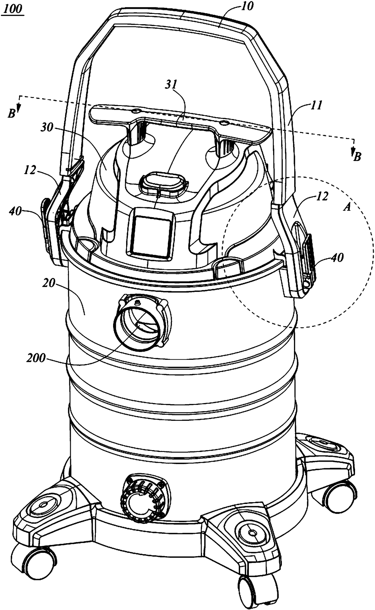
[0057] Such as figure 1 and figure 2 As shown, an embodiment of the present invention discloses a cleaning tool 100, and the cleaning tool 100 can be specifically configured as a bucket type wet and dry vacuum cleaner. The cleaning tool 100 includes a working head assembly (not shown), a body assembly, a handle assembly 10 and a driving assembly. Wherein, the working head assembly includes any one of ground brush, round brush, dust brush, flat suction or other types of brushes or suction heads, and the working head assembly is connected to the fuselage assembly through a hose. Interface 200; the fuselage assembly includes a fuselage body; the handle assembly 10 is connected to the fuselage body through a first connecting shaft 22, and the handle assembly 10 can rotate around a first axis X relative to the fuselage body , which includes a handle body 11 for the operator to hold.

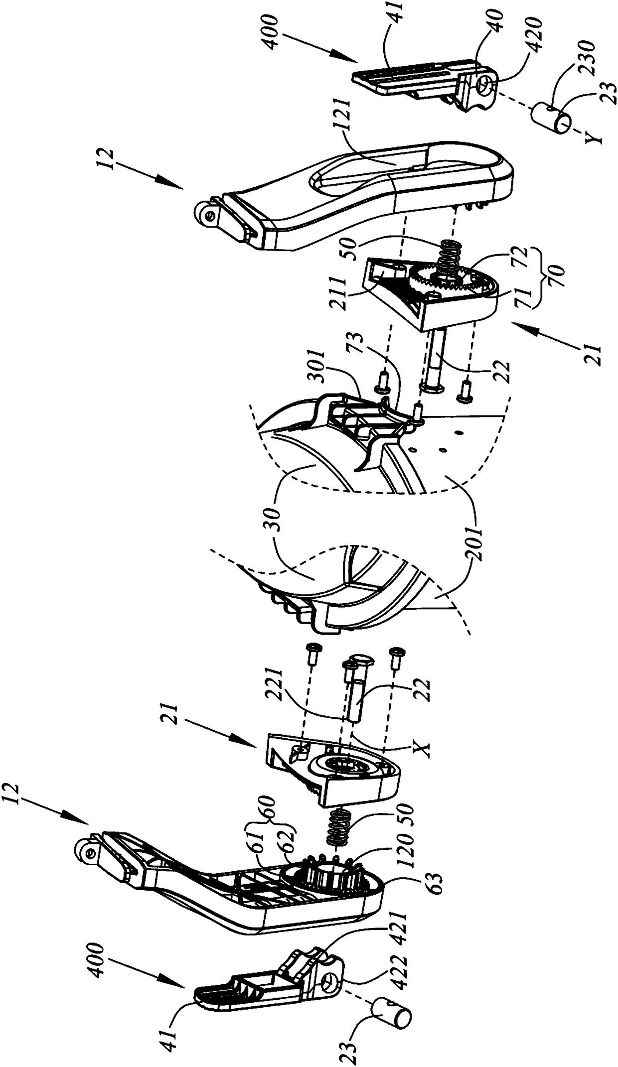
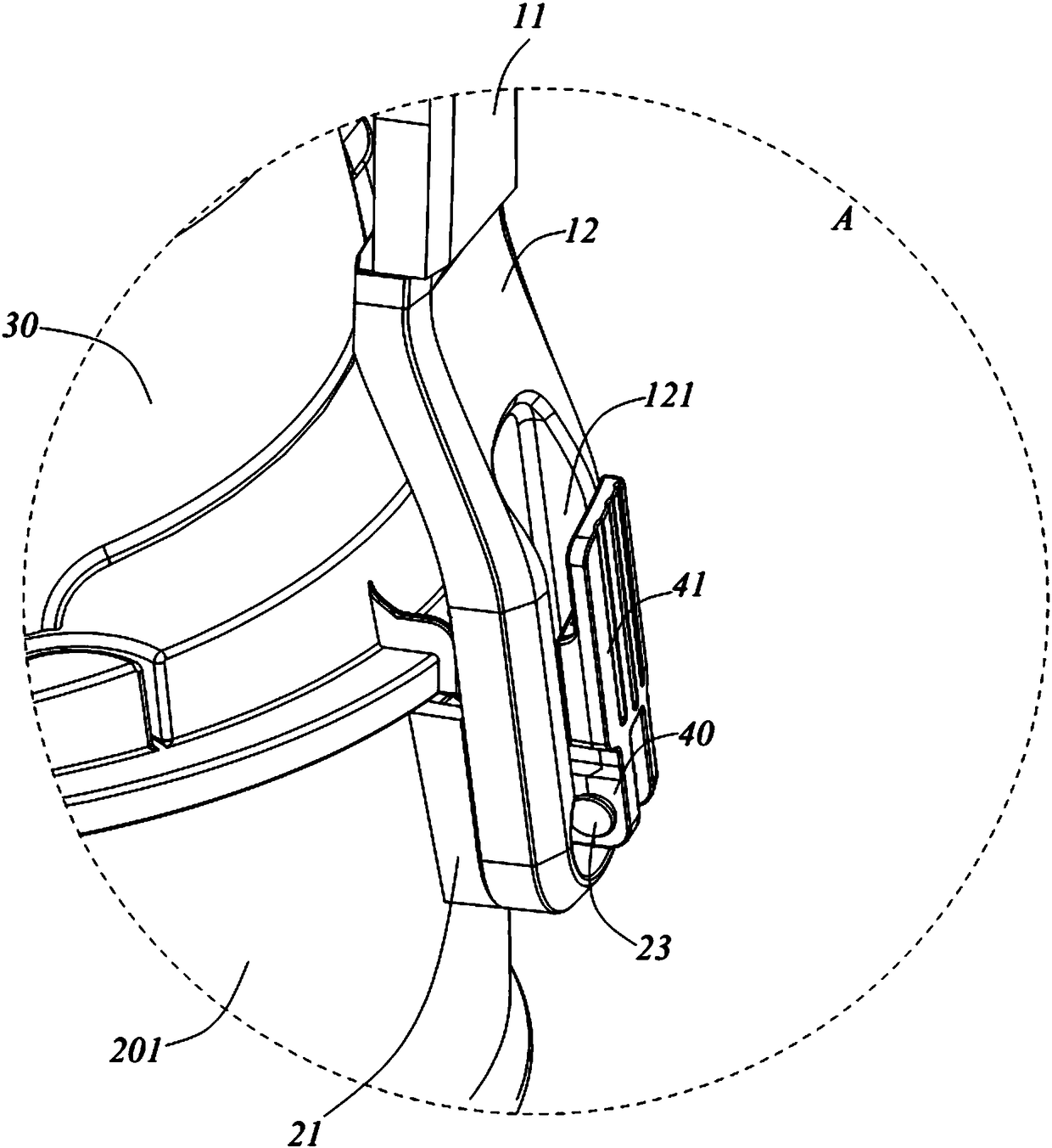
[0058] ginseng Figure 1 to Figure 8 , the cleaning tool 100 has a locked state and a release...

Embodiment 2

[0088] see Figure 9 to Figure 11 , another embodiment of the present invention, this embodiment discloses a cleaning tool. The cleaning tool includes a handle assembly, a body assembly, a driving assembly, a working head assembly and an unlocking mechanism. The difference between the cleaning tool 100 in this embodiment and the cleaning tool 100 in Embodiment 1 lies in the structure of the handle assembly, the structure of the drive assembly, the structure of the unlocking mechanism and the structure of the limit mechanism. These differences will be introduced below , other components / structures that are the same as those in Embodiment 1 will not be repeated here.

[0089] In this embodiment, the handle assembly 10' includes a handle body 11' for the operator to hold, and a positioning mechanism 12' connected to the handle body 11'.

[0090] Specifically, the handle body 11' includes a U-shaped piece 111, a first support piece 112 connected to the end of the U-shaped piece ...


PUM


Abstract

The invention discloses a cleaning tool. The cleaning tool comprises a machine body assembly, a handle assembly and a driving mechanism, wherein the machine body assembly comprises a machine body andlimiting mechanisms arranged on the machine body; the handle assembly is rotationally connected to the machine body around the first axis, and comprises a handle body for holding and positioning mechanisms connected to the handle body, and the positioning mechanisms can reciprocate between a first position and a second position; the driving assembly is movably matched with the positioning mechanisms and used for locking the positioning mechanisms to the second position; when the positioning mechanisms are located at the second position, the positioning mechanisms are matched with the limitingmechanisms so that the handle assembly and the machine body can be mutually limited; when the positioning mechanisms are located at the first position, the positioning mechanisms are separated from the limiting mechanisms so that mutual limiting between the handle assembly and the machine body is released.

Description

technical field [0001] The invention relates to a cleaning tool and belongs to the technical field of small household appliance manufacturing. Background technique [0002] Current cleaning tools, especially wet and dry vacuum cleaners, usually include a body component and a handle movably connected to the body component, and the handle can facilitate the operator to move the body component during use. However, the current handle components are free to rotate and cannot be positioned, causing the handle to shake easily during use, which is not convenient for stable force application during the movement of the fuselage components; moreover, the handle cannot be fixed at multiple angles . In addition, the handle only has the function of being held by the user to lift the vacuum cleaner, which requires additional components to limit and fix the machine head. This will lead to a problem, that is, if the vacuum cleaner is lifted by the user when the machine head is not locked, ...

Claims


Application Information

Patent Timeline
IPC IPC(8): A47L9/32A47L9/00
CPCA47L9/00A47L9/327
Inventor 卞小贤邢振宇刘海平李迎亮
Owner SUZHOU CLEVA PRECISION MACHINERY & TECH
Why Eureka
Try Eureka