Multifunctional filter press

A filter press, multi-functional technology, applied in the fields of filtration and separation, water/sludge/sewage treatment, sludge treatment, etc., can solve the problem of inconvenient disassembly of the filter plate, etc., and achieve the effect of ensuring stability and convenient operation.

Pending Publication Date: 2018-06-12
浙江精鼎电力设备有限公司
View PDF0 Cites 3 Cited by
  • Summary
  • Abstract
  • Description
  • Claims
  • Application Information

AI Technical Summary

Problems solved by technology

[0002] The filter press is the main device of sewage treatment equipment. Its function is to separate the solid and liquid of the waste mud sewage, and the filter plate is the core component of the filter press. Therefore, when a filter plate is damaged, people should replace the filter plate in time. However, in the prior art, when people replace the filter plate, they often use a sling to fasten the filter plate, hang the sling on the crane, and drive the sling and the filter plate to rise synchronously through the crane, so that one filter plate and multiple The filter plate is disassembled, and when the sling is fastened to the filter plate, since the filter plates of multiple filter presses are placed side by side, and the gap between two adjacent filter plates is too small, the sling is fastened to the filter that needs to be replaced. When lifting the plate, the sling is fastened to the adjacent filter plate, causing the two adjacent filter plates to collide when the crane is pulling the sling up, which makes it inconvenient for people to disassemble the filter plate

Method used


Image

  • Multifunctional filter press
  • Multifunctional filter press
  • Multifunctional filter press

Examples


Embodiment Construction

[0028] The following are specific embodiments of the present invention and in conjunction with the accompanying drawings, the technical solutions of the present invention are further described, but the present invention is not limited to these embodiments.

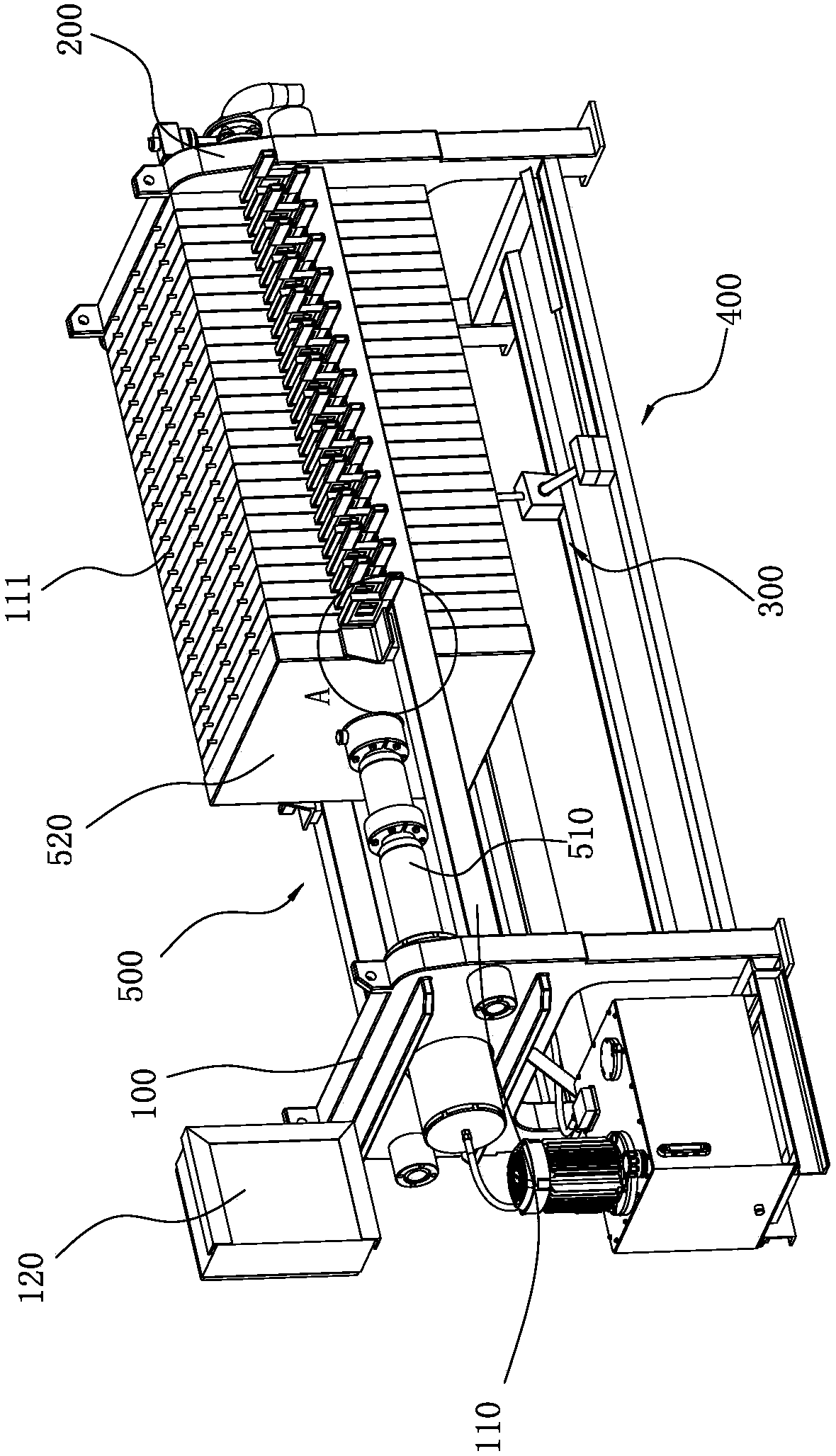
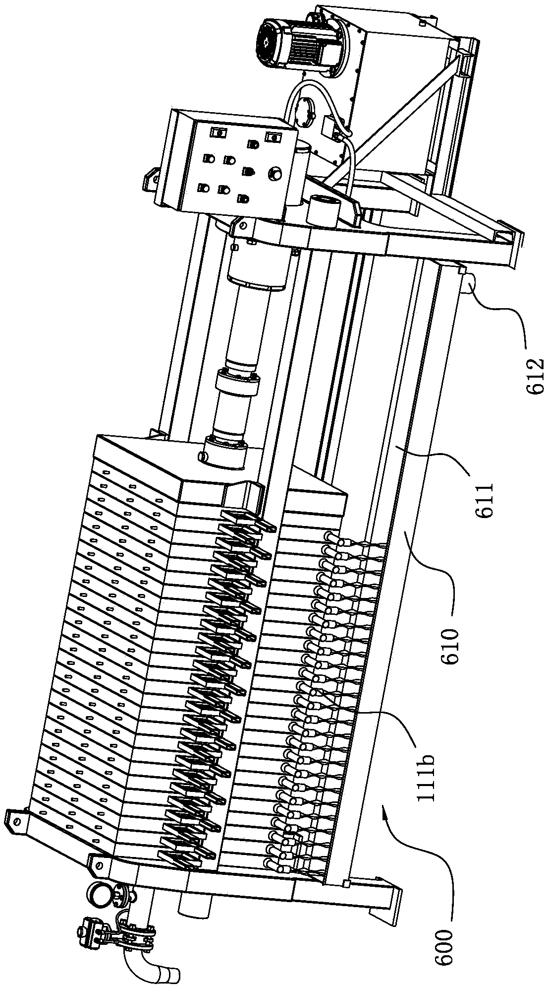
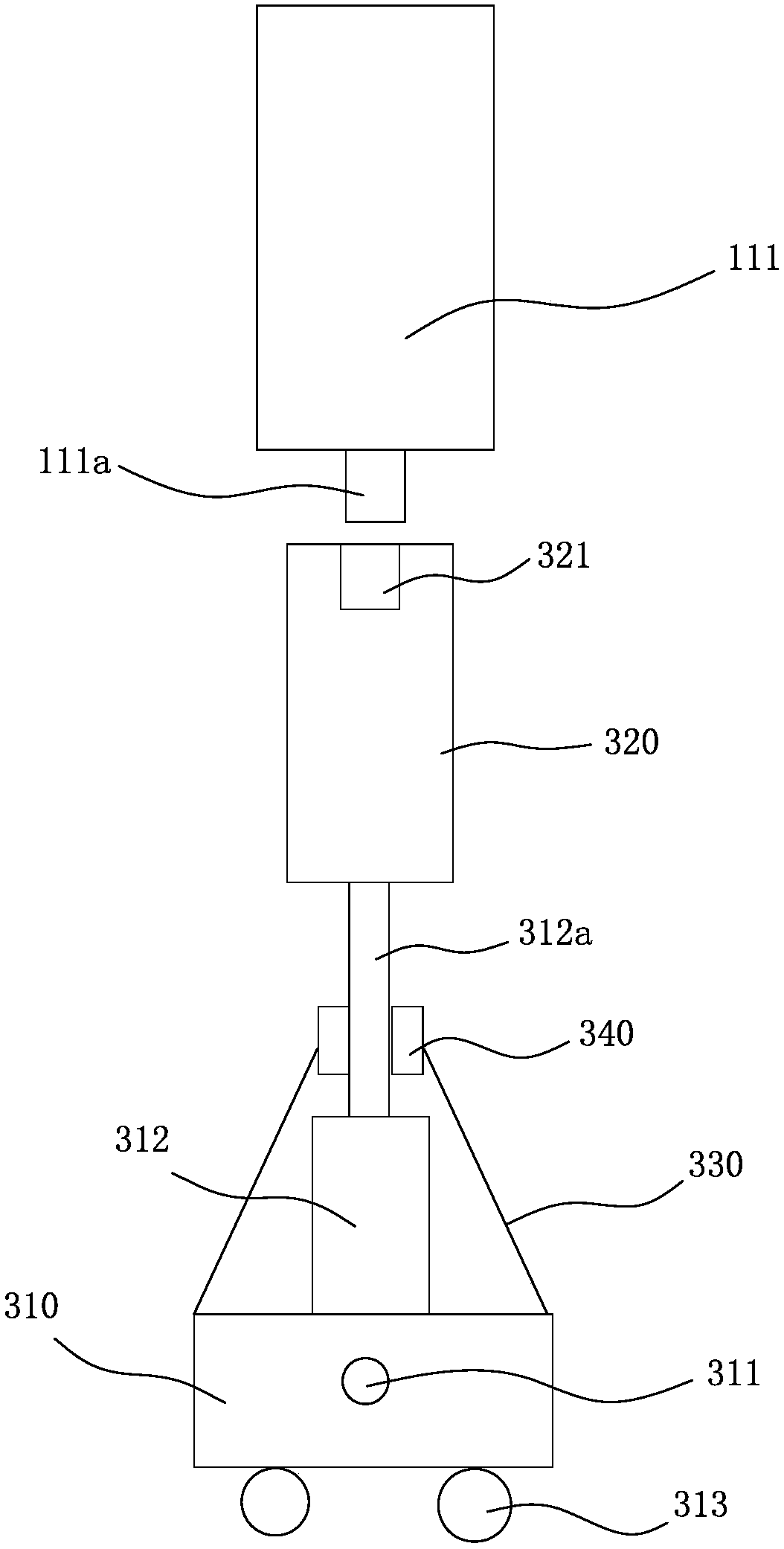
[0029] Such as figure 1 — Image 6 As shown, a multifunctional filter press of the present invention includes a front seat 100, a rear seat 200, a guide rod 110, a filter plate 111, a push plate mechanism 300, a movable seat 320, a first oil cylinder 312, a piston rod 312a, a top plate 320, a The dust cover 330 , the fastening mechanism 400 , the pressing device 500 , the drainage mechanism 600 and the controller 120 .

[0030] One side of the front seat 100 is provided with a rear seat 200, and two guide rods 110 are interposed between the front seat 100 and the rear seat 200, and a plurality of filter plates 111 are clamped between the two guide rods 110. A plurality of filter plates 111 are fastened to the pressing de...


PUM


Abstract

The invention provides a multifunctional filter press, and belongs to the technical field of sewage treatment equipment. By the aid of the multifunctional filter press, the problem that filter platesof existing filter presses are inconvenient to change can be solved. The multifunctional filter press comprises a front seat, a rear seat, guide rods, a plurality of filter plates, a push plate mechanism, movable seats, first oil cylinders, piston rods, ejecting plates, dustproof sleeves, a tightening mechanism, a compressing device, a drainage mechanism and a controller. The multifunctional filter press has the advantages that the push plate mechanism and the tightening mechanism can be simultaneously controlled by the controller, so that the filter plates required to be changed can be liftedup from the multiple filter plates by the push plate mechanism, and hang ropes can be conveniently fastened by people; every two adjacent filter plates can be prevented from being collided with eachother, and accordingly the filter plates can be protected; the controller is arranged on the front seat, the movable seats, the first oil cylinders, the tightening mechanism and the compressing deviceare electrically connected to the controller, accordingly, automation of the multifunctional filter press can be embodied, and operation can be facilitated.

Description

technical field [0001] The invention belongs to the technical field of sewage treatment equipment and relates to a multifunctional filter press. Background technique [0002] The filter press is the main device of sewage treatment equipment. Its function is to separate the solid and liquid of the waste mud sewage, and the filter plate is the core component of the filter press. Therefore, when a filter plate is damaged, people should replace the filter plate in time. However, in the prior art, when people replace the filter plate, they often use a sling to fasten the filter plate, hang the sling on the crane, and drive the sling and the filter plate to rise synchronously through the crane, so that one filter plate and multiple The filter plate is disassembled, and when the sling is fastened to the filter plate, since the filter plates of multiple filter presses are placed side by side, and the gap between two adjacent filter plates is too small, the sling is fastened to the f...

Claims


Application Information

Patent Timeline
IPC IPC(8): B01D25/12C02F11/12
CPCB01D25/003B01D25/12C02F11/122
Inventor 朱墨
Owner 浙江精鼎电力设备有限公司
Why Eureka
Try Eureka