
Paperboard laminating slitting device
A technology for laminating and cardboard, applied in lamination devices, layered products, lamination auxiliary operations, etc., can solve the problems of uneven tearing, low efficiency and high labor cost, and achieve the effect of flushing lamination incisions
- Summary
- Abstract
- Description
- Claims
- Application Information
AI Technical Summary
Problems solved by technology
Method used
Image

Examples
Embodiment Construction
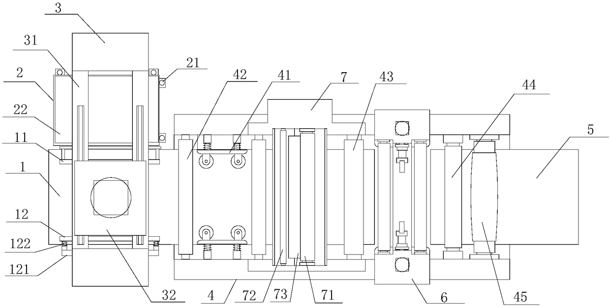
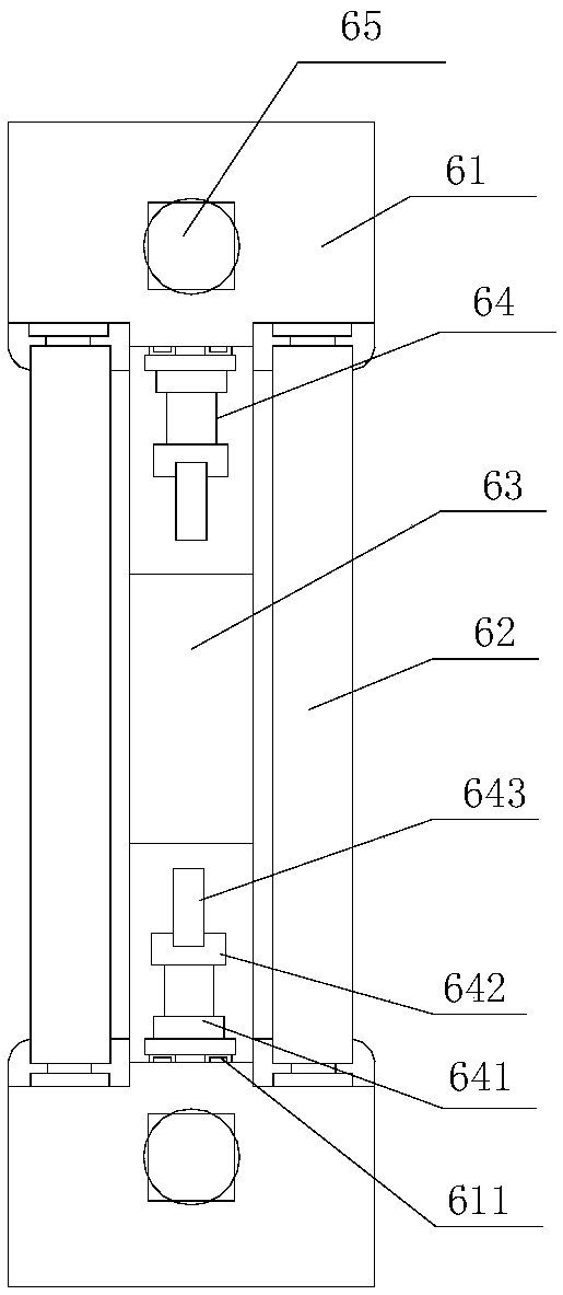
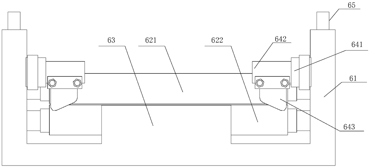
[0017] refer to Figure 1 to Figure 4 , a cardboard coating cutting device of the present invention, comprising a first conveyor belt mechanism 1, a material storage mechanism 2, a mechanical claw conveying mechanism 3, a frame 4, a second conveyor belt mechanism 5, a cutting mechanism 6 and a film coating mechanism 7, The mechanical claw conveying mechanism 3 spans the first conveyor belt mechanism 1 and the material storage mechanism 2, and the mechanical claw conveying mechanism 3 is provided with a feeding sucker mechanism, and the two ends of the frame 4 are respectively provided with a first conveyor belt mechanism 1 and the second conveyor belt mechanism 5, a coating mechanism 7 is arranged between the first conveyor belt mechanism 1 and the second conveyor belt mechanism 5, and the introduction roller assembly 42, the coating mechanism 7, and the lead-out roller assembly 42 are sequentially arranged on the frame 4 Roller assembly 43, slitting mechanism 6, auxiliary pin...
PUM
 Abstract
Description
Claims
Application Information