A slitting and conveying device for a laminating machine

A technology of conveying device and laminating machine, which is applied in the directions of transportation and packaging, layered products, thin material processing, etc. It can solve the problems of low production efficiency, uneven tearing, adhesion, etc., and achieve thorough cooling and flat film incision. neat, simple operation

Inactive Publication Date: 2019-03-05
滁州市雪山粮油机械制造有限公司
View PDF12 Cites 0 Cited by
  • Summary
  • Abstract
  • Description
  • Claims
  • Application Information

AI Technical Summary

Problems solved by technology

Due to the use of hot pressing lamination technology, the surface temperature of the printed matter is generally high. When the next printed matter is delivered, the surface will not be cooled and will cause adhesion, which will affect the quality of the product; Transportation to the next process greatly wastes manpower, resulting in problems such as low production efficiency and increased cost. The manual tearing method in the existing laminating machine has the following problems. On the one hand, the efficiency is low and the labor cost is high; Tearing can easily cause quality problems such as uneven tearing, so a cutting and conveying device for the laminating machine is proposed

Method used


Image

  • A slitting and conveying device for a laminating machine
  • A slitting and conveying device for a laminating machine
  • A slitting and conveying device for a laminating machine

Examples


Embodiment Construction

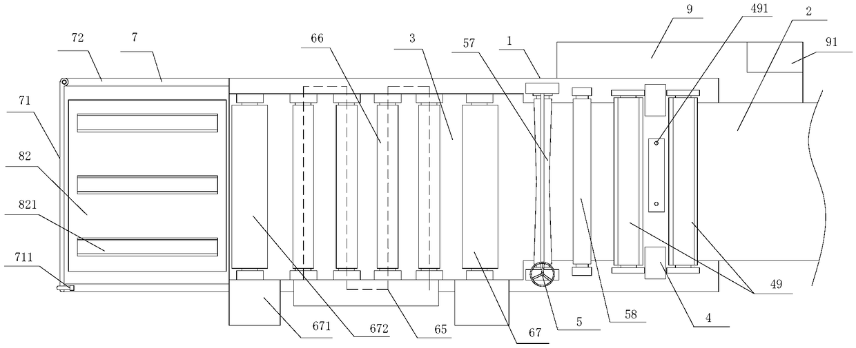
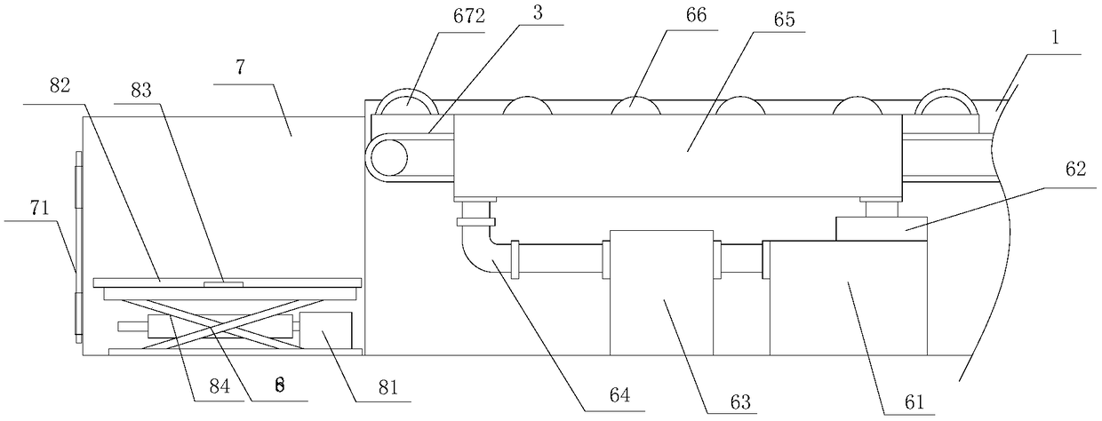
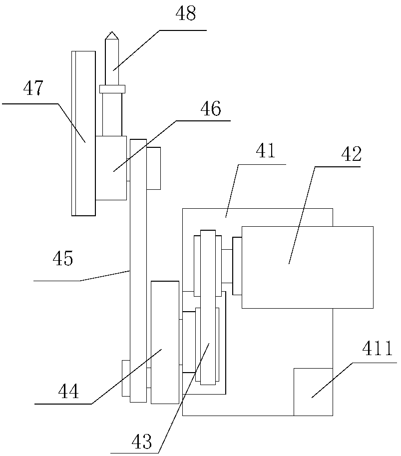
[0015] refer to Figure 1 to Figure 4A slitting and conveying device for a laminating machine in the present invention includes a frame 1, a first conveyor belt mechanism 2, a second conveyor belt mechanism 3, a slitting device 4, a slitting roller assembly 5, a cooling circulation device 6, a feeding box 7, Lifting platform device 8 and servo control box 9, described frame 1 is provided with first conveyor belt mechanism 2, second conveyor belt mechanism 3, is provided with cutting device between described first conveyor belt mechanism 2, second conveyor belt mechanism 3 4. The first conveying roller assembly 49 is provided on both sides of the cutting device 4, and several cooling roller assemblies 66 and two second conveying roller assemblies 67 are arranged on the cooling circulation device 6. The cooling roller assembly 66 is evenly distributed between the two second conveying roller assemblies 67, the slitting roller assembly 5 is provided with a slitting pressing roller...


PUM


Abstract

The invention provides a slitting and conveying device for a laminating machine. The slitting and conveying device comprises a rack, a first conveyor belt mechanism, a second conveyor belt mechanism, a slitting device, a slitting roller assembly, a cooling circulating device, a discharging tank, a lifting platform device and a servo control box. The first conveyor belt mechanism and the second conveyor belt mechanism are arranged on the rack. The slitting device is arranged between the first conveyor belt mechanism and the second conveyor belt mechanism. First conveying roller assemblies, an auxiliary pressing roller, a slitting pressing roller, second conveying roller assemblies and a cooling roller assembly are sequentially arranged above the second conveyor belt mechanism in the operating direction. The discharging tank is arranged on one side of the second conveyor belt mechanism. The lifting platform device is arranged in the discharging tank. Shearing is conducted from the two sides by the adoption of the slitting roller assembly, it is guaranteed that laminated notches are flush with each other, a lifting platform is arranged in the discharging tank, the vertical movement of storage trays is controlled according to the needs, it is guaranteed that laminated plates on conveyor belts smoothly fall into the storage trays, the storage trays are transferred through a hand-operated fork lift, and the operation is simple.

Description

【Technical field】 [0001] The invention relates to the technical field of laminating machines, in particular to a cutting and conveying device for a laminating machine. 【Background technique】 [0002] The laminating process is a surface finishing process for processing the surface of the printed matter, also known as post-press overmolding or post-press film, which refers to covering a layer of 0.012-0.020mm thick on the surface of the printed matter with a laminating machine. The transparent plastic film forms a product processing technology combining paper and plastic. The existing laminating machine presses printed matter such as plastic film and paper together to improve the gloss and fastness of the printed matter, and to play protective functions such as waterproof, antifouling, and chemical corrosion resistance. The existing laminating machine mainly includes a film feeding device, a conveyor belt, and a hot pressing device. The plastic film is led to the feeding port...

Claims


Application Information

Patent Timeline
Patent Type & Authority Patents(China)
IPC IPC(8): B26D1/06B26F3/00B26D5/00B65H20/02B32B38/00
CPCB26D1/065B26D5/00B26F3/002B32B38/0004B65H20/02
Inventor 周凯姚悦杨艳沛朱明江李嘉渊
Owner 滁州市雪山粮油机械制造有限公司
Why Eureka
Try Eureka