Automatic chopstick detachment machine

An automatic and driving mechanism technology, which is applied in the direction of manufacturing tools, metal processing, metal processing equipment, etc., can solve the problems that combined chopsticks cannot be recycled again, difficult to disassemble, and high scrap rate, so as to achieve strong equipment reliability, high processing efficiency, The effect of low scrap rate

Active Publication Date: 2018-11-09
成都中箸筷业有限公司
View PDF5 Cites 3 Cited by
  • Summary
  • Abstract
  • Description
  • Claims
  • Application Information

AI Technical Summary

Problems solved by technology

[0004] After the combined chopsticks are used, it is necessary to remove the used bamboo part 2, clean the plastic part 1, and then install a new bamboo part 2. The existing production process relies on the production personnel to manually remove the bamboo part 2 from the plastic part 1. It is very laborious and time-consuming to disassemble the connecting tube 3, and it is easy to remove the connecting tube 3 from the plastic part 1 during the manual disassembly process, so that the combined chopsticks cannot be recycled again, and the scrap rate during the disassembly process is high

Method used


Image

  • Automatic chopstick detachment machine
  • Automatic chopstick detachment machine
  • Automatic chopstick detachment machine

Examples


Embodiment 1

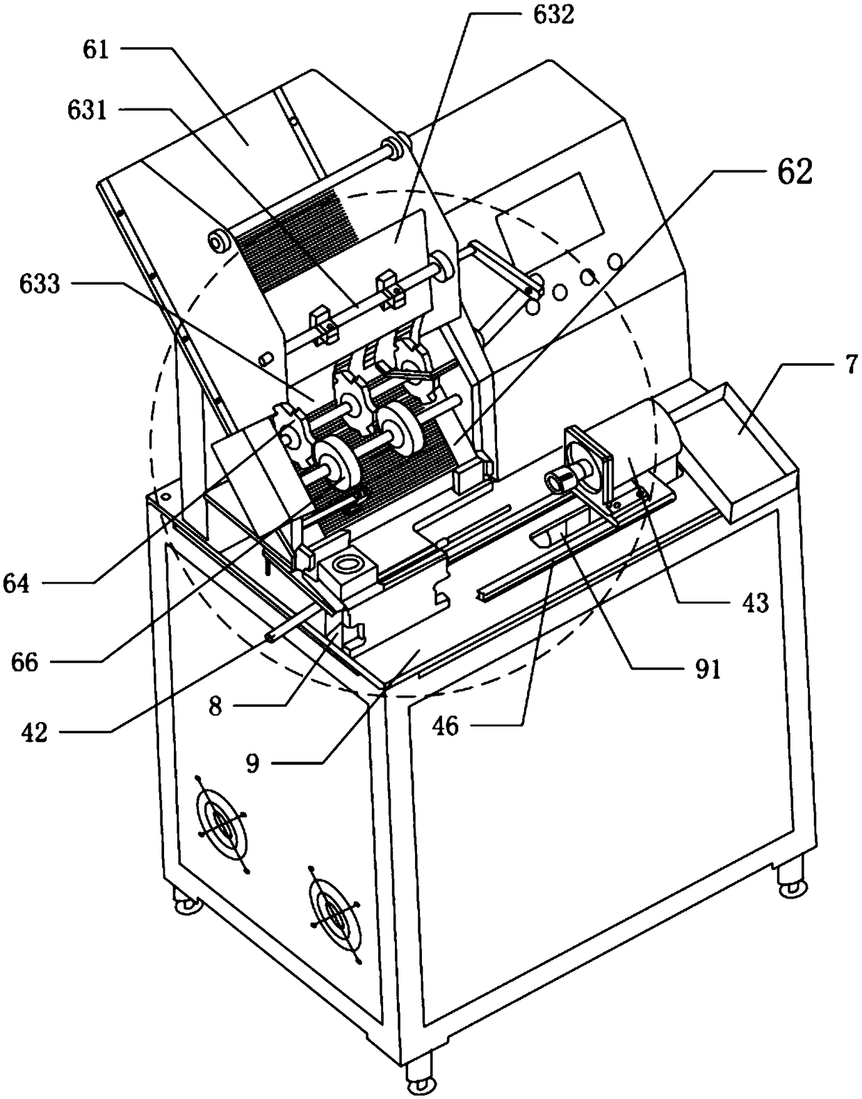
[0041] This embodiment provides an automatic chopsticks removal machine, comprising a feeding mechanism 6, a transfer mechanism 5 and a chopsticks removal assembly 4, the combined chopsticks are placed in the feeding mechanism 6, the feeding mechanism 6 is used to provide combined chopsticks, and the transfer mechanism 5 is used Between the combined chopsticks discharged from the feeding mechanism 6 are transferred to the chopsticks removal assembly 4, the chopsticks removal assembly 4 is used to remove the bamboo part 2 from the combination chopsticks.

[0042] Specifically, such as figure 2 and image 3As shown, the chopsticks removing assembly 4 includes a first driving mechanism 41, a chopsticks pushing device 42, a chopsticks holding mechanism 44 and a chopsticks removing motor 43, and the chopsticks holding mechanism 44 is used to fix the bamboo part 2 of the combined chopsticks. The chopsticks removal motor 43 is a hollow shaft motor, the chopsticks locking mechanism ...

Embodiment 2

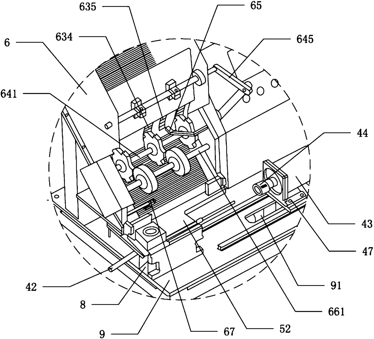
[0044] This embodiment provides an automatic chopsticks removal machine, comprising a feeding mechanism 6, a transfer mechanism 5 and a chopsticks removal assembly 4, the combined chopsticks are placed in the feeding mechanism 6, the feeding mechanism 6 is used to provide combined chopsticks, and the transfer mechanism 5 is used Between the combined chopsticks discharged from the feeding mechanism 6 are transferred to the chopsticks removal assembly 4, the chopsticks removal assembly 4 is used to remove the bamboo part 2 from the combination chopsticks.

[0045] Specifically, such as Figure 4 and Figure 5 As shown, the chopsticks removing assembly 4 includes a first driving mechanism 41, a chopsticks pushing device 42, a chopsticks holding mechanism 44 and a chopsticks removing motor 43. The motor 43 is fixedly connected with the mount 49, the rotating shaft of the chopsticks motor 43 passes through the mount 49, the shell of the chopsticks motor 43 is fixedly connected wit...


PUM


Abstract

The invention discloses an automatic chopstick detachment machine. The automatic chopstick detachment machine comprises a feeding mechanism, a transfer mechanism and a chopstick detachment assembly, wherein combined chopsticks are placed in the feeding mechanism; the feeding mechanism is used for providing the combined chopsticks; the transfer mechanism is used for transferring the combined chopsticks discharged by the feeding mechanism to the space of the chopstick detachment assembly; and the chopstick detachment assembly is used for detaching bamboo parts from the combined chopsticks. Withthe adoption of automatic chopstick detachment equipment, the chopstick detachment speed is increased, and the amount of wastes generated in a chopstick detachment process is reduced; and a chopstickdetachment procedure can further be better matched with upstream automatic production equipment and downstream automatic production equipment, so that production control is facilitated.

Description

technical field [0001] The invention belongs to the technical field of catering equipment, and in particular relates to an automatic chopsticks dismantling machine. Background technique [0002] Disposable hygienic chopsticks commonly used in the catering industry currently use a large amount of wood to be processed into disposable chopsticks after standard processing. Diners have multiple needs in different dining environments. [0003] This situation gave birth to the widespread use of combination chopsticks, such as figure 1 As shown, the existing combined chopsticks include a plastic part 1 and a bamboo part 2, the cross section of the plastic part 1 is square, and the cross section of the bamboo part 2 is circular, and the end of the plastic part 1 connects with the bamboo part through a socket 3. The ends of the mass part 2 are connected, and the inner wall of the socket pipe 3 is provided with threads. When in use, the plastic part 1 is used as a grip part, and the...

Claims


Application Information

Patent Timeline
Patent Type & Authority Applications(China)
IPC IPC(8): B23P19/04
CPCB23P19/001B23P19/004B23P19/04B29B2017/0217
Inventor 邹洪
Owner 成都中箸筷业有限公司
Why Eureka
Try Eureka