Damping shock absorber and manufacturing method thereof

A shock absorber and damping technology, used in springs/shock absorbers, vibration suppression adjustment, mechanical equipment, etc., can solve the problem of insignificant radial vibration shock absorption, reduce vibration and noise, and reduce resonance frequency Effect

Pending Publication Date: 2018-06-12
ERZHONG DEYANG POWER TECH CO LTD
View PDF1 Cites 7 Cited by
  • Summary
  • Abstract
  • Description
  • Claims
  • Application Information

AI Technical Summary

Problems solved by technology

[0006] In view of this, the present invention provides a damping shock absorber and its manufacturing method to solve the problem that the existing damping shock absorber has no obvious effect on radial vibration damping of the motor rotor in the flywheel accumulator

Method used


Image

  • Damping shock absorber and manufacturing method thereof
  • Damping shock absorber and manufacturing method thereof
  • Damping shock absorber and manufacturing method thereof

Examples


Embodiment 1

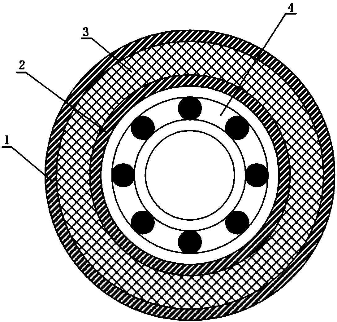
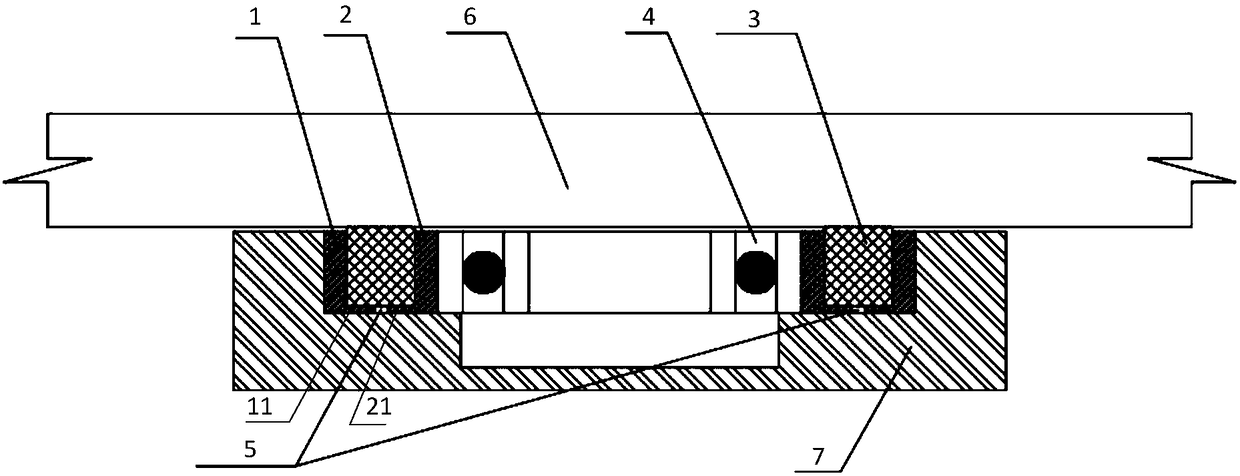
[0034] In this embodiment a damping shock absorber is provided, such as figure 1 As shown, the damping shock absorber includes an inner ring 2, an elastic shock absorber 3 and an outer ring 1 that are sequentially installed and fixed along the bearing 4 from the inside to the outside. The elastic shock absorber 3 has a radial A deformed spatial structure. Specifically, in the radial direction of the bearing 4, the inner ring 2, the elastic shock absorber 3 and the outer ring 1 are sequentially installed and fixed from the inside to the outside. During the operation of the equipment, the elastic shock absorber 3 can move in the radial direction. Deformation under force can eliminate vibration and noise generated in the radial direction of the equipment, especially for a flexible rotor operating at a supercritical speed such as a flywheel accumulator. The deformation produced by the elastic shock absorber 3 in the can reduce the low-order resonance frequency of the rotor, so th...

Embodiment 2

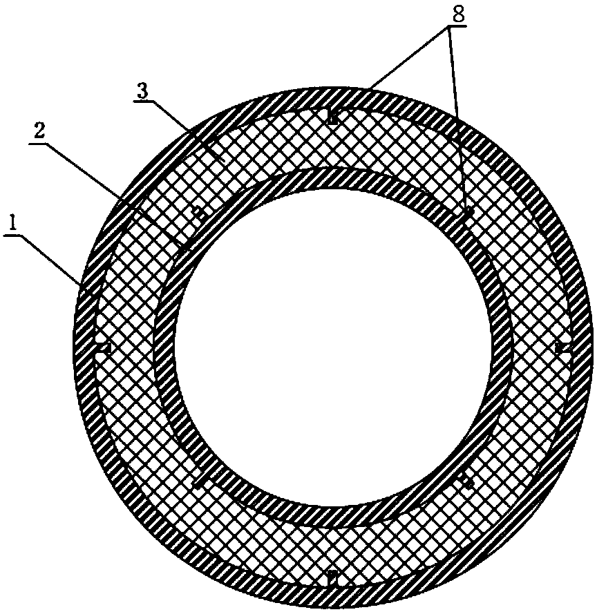
[0043] In this embodiment, a method for manufacturing a damping shock absorber is provided, specifically: processing the metal material into a double-layer cylindrical structure that allows the bearing 4 to pass through, and the middle of the double-layer cylindrical structure is an elastic shock absorber 3, the size of the accommodation space is determined according to the size of the bearing, and the installation requirements of the bearing shall prevail. Then, on the side walls of the inner ring 2 and the outer ring 1 facing the elastic shock absorbing element 3, several protrusions 8 for preventing the mutual movement of the inner ring 2, the outer ring 1 and the elastic shock absorbing element 3 are arranged at intervals. And an opening is provided on the other horizontal end surface of the double-layer cylindrical structure, and the opening is the installation entrance of the elastic shock absorbing element 3 . Then the woven and wound elastic shock absorber 3 is extrude...


PUM


Abstract

The invention provides a damping shock absorber comprising an inner ring (2), an elastic shock absorption part (3) and an outer ring (1) which are installed fixedly and sequentially from inside to outside in the radial direction of a bearing (4). The elastic shock absorption part (3) is of a space structure which deforms in the radial direction of the bearing (4) when subjected to the action of external force. The invention further provides a method for manufacturing the damping shock absorber. The damping shock absorber is installed in the radial direction of the bearing (4). The inner ring (2), the elastic shock absorption part (3) and the outer ring (1) are arranged sequentially along the bearing (4) from inside to outside. During operation of equipment, shock in the radial direction ofthe equipment can be eliminated through the elastic shock absorption part (3), particularly for a flywheel accumulator, resonant frequency can be lowered through the damping shock absorber in the radial direction of the bearing (4), the elastic shock absorption part (3) can be stressed and deforms in the radial direction, shock and noise can be reduced, the effect that a rotor goes over a resonance point smoothly is ensured, and high-speed operation is achieved.

Description

technical field [0001] The invention relates to the technical field of shock absorbers, in particular to a damping shock absorber and a manufacturing method thereof. Background technique [0002] Flywheel energy storage system stores electrical energy, as an alternative to chemical batteries and supercapacitors, it has the advantages of long life, low maintenance, high efficiency and high power. The principle of flywheel energy storage is to rely on the motor to realize charging and discharging, and rely on the rotating flywheel to store energy. When charging, the motor drives the flywheel to rotate, and the flywheel converts electrical energy into kinetic energy and stores it; when discharging, the flywheel drives the motor to convert kinetic energy into electrical energy and release it. During energy storage, the flywheel energy E∝ρvs 2 , where ρ is the density of the rotor material, v is the size of the rotor, and s is the linear velocity of the rotor edge. Therefore, t...

Claims


Application Information

Patent Timeline
Patent Type & Authority Applications(China)
IPC IPC(8): F16F15/133
CPCF16F15/133
Inventor 不公告发明人
Owner ERZHONG DEYANG POWER TECH CO LTD
Why Eureka
Try Eureka