Valve seat fixing structure of high pressure steam valve

A fixed structure, high-pressure steam technology, applied in the direction of valve lift, valve details, valve device, etc., can solve the problems that cannot meet the application, affect the sealing of the bottom gasket of the valve seat, internal leakage, etc., achieve simple structure and high maintenance utilization rate , the effect of improving economic efficiency

Inactive Publication Date: 2018-06-12
WUXI SMART AUTO CONTROL ENG CO LTD
View PDF6 Cites 1 Cited by
  • Summary
  • Abstract
  • Description
  • Claims
  • Application Information

AI Technical Summary

Problems solved by technology

At this time, the loose valve seat will definitely have a relative displacement in the axial direction, which will affect the sealing of the gasket at the bottom of the valve seat and cause internal leakage.
It can be concluded from this that neither the threaded seat structure nor the pressure sleeve structure can meet the application of this working condition.

Method used


Image

  • Valve seat fixing structure of high pressure steam valve
  • Valve seat fixing structure of high pressure steam valve

Examples


Embodiment Construction

[0018] The specific embodiments of the present invention will be further described below in conjunction with the accompanying drawings.

[0019] The present invention will be further described below in conjunction with specific drawings and embodiments.

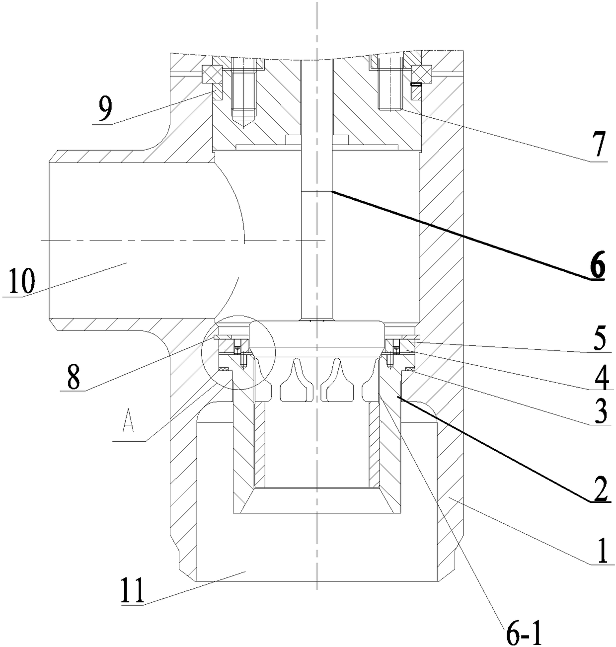
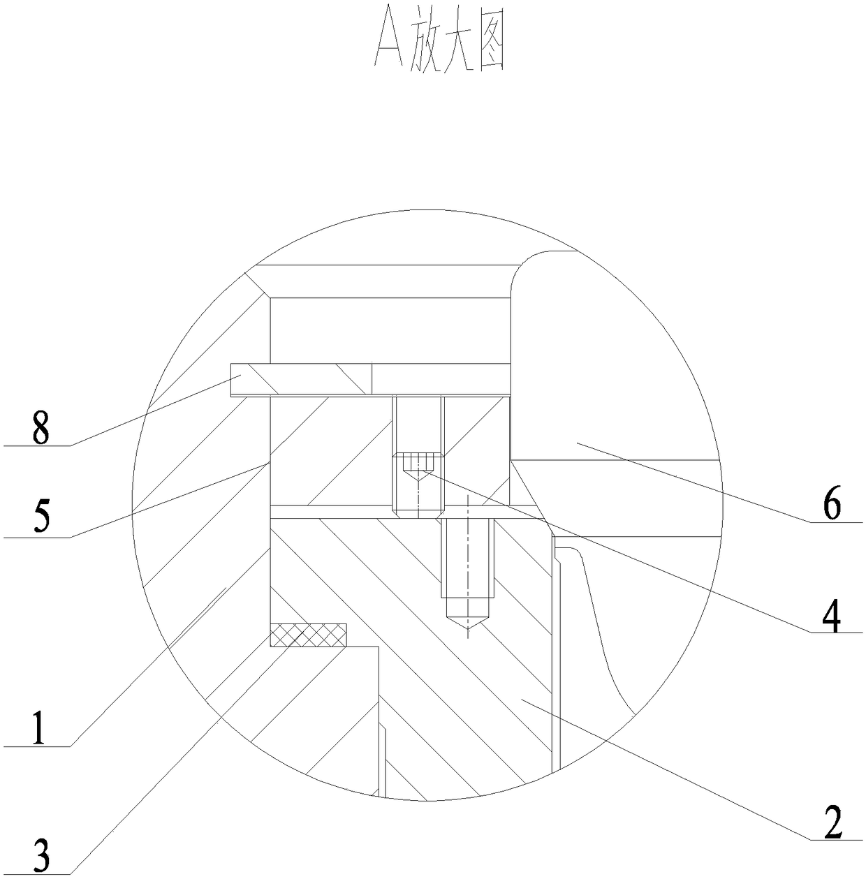
[0020] like figure 1 and figure 2 As shown: the present invention includes a valve body 1, one end of the valve body 1 is provided with an inlet channel 11 for fluid entry, and the other end of the valve body 1 is provided with an outlet channel 10 for fluid outflow, and in the valve body 1 A valve body cavity is also provided, and the valve body cavity is located between the inlet flow channel 11 and the outlet flow channel 10, and a positioning step surface for installing the valve seat 2 is provided at the bottom of the cavity of the valve body 1, so that the valve seat 2 is restricted in the valve The movement inside the body 1 in the radial direction, the valve core assembly 6 that can move linearly along the inner wa...


PUM


Abstract

The invention belongs to the technical field of valve bodies and relates to a valve seat fixing structure of a high pressure steam valve. The valve seat fixing structure of the high pressure steam valve comprises a valve body, wherein an inlet runner where a fluid enters and an outlet runner where the fluid flows out are formed in one end of the valve body, a valve body cavity is arranged betweenthe inlet runner and the outlet runner correspondingly in the valve body, a valve seat is mounted on a valve body cavity positioning step face, a valve element assembly is arranged in the valve seat,and the valve element assembly can more linearly along the inner wall of the valve seat; the inlet runner and the outlet runner are arranged vertical to each other, and when the valve element assemblymoves in the valve seat, the communicating state of the inlet runner and the outlet runner is adjusted; a valve cover is arranged on the axial side, opposite to the inlet runner, on the valve body, filler is arranged between the valve cover and the valve body, and a valve rod of the valve element assembly penetrates through a guide hole in the valve cover. The valve seat fixing structure is relatively low in processing precision, convenient to disassemble and assemble and maintain and reliable in sealing effect.

Description

technical field [0001] The invention belongs to the technical field of valve bodies, and relates to a high-pressure steam valve seat fixing structure. Background technique [0002] The high-pressure steam valve is a device operated by power to regulate high-pressure steam in the process control system. The high-pressure steam valve changes the position of the retaining element in the valve according to the signal sent by the control system, and then adjusts the flow, temperature, liquid level and pressure of the high-pressure steam to meet the needs of the entire system. At present, the traditional valve seat fixing structures usually only have two types: threaded type and compression sleeve type. The threaded valve seat generally has a relatively large thread size, and it cannot be manually tightened to achieve the goal of fixing the valve seat and gasket seal. At the same time, because the valve seat is in a high temperature state for a long time, the thread is prone to ...

Claims


Application Information

Patent Timeline
Patent Type & Authority Applications(China)
IPC IPC(8): F16K1/00F16K1/32F16K41/02F16K1/42
CPCF16K1/00F16K1/32F16K1/427F16K41/02
Inventor 陆坤铭陈彦张志超
Owner WUXI SMART AUTO CONTROL ENG CO LTD
Why Eureka
Try Eureka