Fabric drying device

A cloth drying and rack technology, which is applied in drying, drying machines, heating devices, etc., can solve the problems of poor drying effect of cloth, and achieve the goal of ensuring safety and stability, good effect and improving quality Effect

Inactive Publication Date: 2018-06-12
吴江市恒达纺织整理有限公司
0 Cites 5 Cited by

AI-Extracted Technical Summary

Problems solved by technology

[0003] The purpose of the present invention is to provide a cloth drying device, which has the advantage of good dr...

Method used

During use, processing personnel only need to make first motor 3 work by external controller, and first motor 3 drives driving wheel 4 to rotate, and driving wheel 4 drives driven wheel 6 to rotate by belt 5, and driven wheel 6 passes movable rod 7 and the bearing seat cooperate to rotate, the synchronous cooperation of the driving wheel 4 and the driven wheel 6 drives the sliding shaft 8 to move, and the sliding shaft 8 drives the heating cylinder 12 to move through the cooperation of the annular groove plate 9, the sliding plate 10 and the chute 11, and the heating cylinder 12 Through the stable movement of the sliding rod 13 and the slideway 14, the heating cylinder 12 dries and heats the cloth after being energized, and the second motor 18 drives the winding wheel 19 to rotate. The cooperation of the winding wheel 19 and the unwinding wheel 16, The cloth is rolled up, thereby achieving the advantage of good drying effect on the cloth.
In sum: this cloth drying device, by driving wheel 4, belt 5, driven wheel 6, movable bar 7, slide shaft 8, annular groove plate 9, slide plate 10, chute 11, heating tube 12, The cooperation of the slide bar 13 and the slideway 14 solves the problem that the existing cloth drying device has a poor drying effect on the cloth.
Please refer to Fig. 1-2, a kind of cloth drying device, comprise frame 1, the both sides of frame 1 bottom are all movably connected with universal wheel 21 by support stand, and the surface of universal wheel 21 is made rubber pad Buffer processing, by setting the universal wheel 21, the flexibility of the device is improved, and it is convenient for the staff to promote, thereby improving the work efficiency of the staff. The frictional force between the ground, thereby prolonging the frictional force between the universal wheel 21 and the ground, the bottom of the left side of the frame 1 is movably connected with the unwinding wheel 16 through the fixed plate 15, and the top of the right side of the frame 1 is passed through the horizontal plate 17 is fixedly connected with a second motor 18, and the output shaft of the second motor 18 is fixedly connected with a winding wheel 19. By setting the fixed plate 15 and the horizontal plate 17, the safety of the unwinding wheel 16 and the winding wheel 19 during operation is guaranteed. and stability, the unwinding wheel 16 and the winding wheel 19 cooperate to achieve the effect of moving the cloth. The surface of the unwinding wheel 16 is connected to the cloth by transmission, and the right side of the cloth runs through the frame 1 and the heating cylinder in turn. 12 a...

Abstract

The invention discloses a fabric drying device which comprises a rack, wherein a box body is welded to the center of the bottom of the cavity of the rack; a first motor is fixedly connected with the left side of the back of the cavity of the box body through a fixing part; the output shaft of the first motor is fixedly connected with a driving wheel; the surface of the driving wheel is in transmission connection with a driven wheel through a belt; a movable rod is welded to the axis of the back of the driven wheel; and the back of the movable rod is movably connected with the inner wall of thebox body through a bearing pedestal. According to the fabric drying device, through cooperation of the driving wheel, the belt, the driven wheel, the movable rod, a sliding shaft, an annular trough plate, a sliding plate, a sliding chute, a heating cylinder, a sliding rod and a slideway, the heating cylinder does reciprocating motion left and right to heat and dry the fabric, so that the advantage that the fabric drying effect is excellent is realized, the fabric drying quality is improved, fabric machining is ensured, the working efficiency of machining staff is improved and the the practicality of the fabric drying device is improved.

Application Domain

Drying machines with progressive movementsHeating arrangement

Technology Topic

EngineeringSlide plate +3

Image

  • Fabric drying device
  • Fabric drying device

Examples

  • Experimental program(1)

Example Embodiment

[0016] The technical solutions in the embodiments of the present invention will be clearly and completely described below with reference to the accompanying drawings in the embodiments of the present invention. Obviously, the described embodiments are only a part of the embodiments of the present invention, but not all of the embodiments. Based on the embodiments of the present invention, all other embodiments obtained by those of ordinary skill in the art without creative efforts shall fall within the protection scope of the present invention.
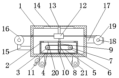
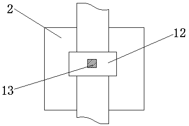
[0017] see Figure 1-2 , a cloth drying device, comprising a frame 1, both sides of the bottom of the frame 1 are movably connected with a universal wheel 21 through a support, and the surface of the universal wheel 21 is treated with rubber pads for buffering, and by setting the universal wheel 21 , the flexibility of the device is improved, and it is convenient for the staff to push, thereby improving the work efficiency of the staff. The rubber pad cushioning treatment of the universal wheel 21 is provided to reduce the friction between the universal wheel 21 and the ground, thereby prolonging the The friction between the universal wheel 21 and the ground, the bottom of the left side of the frame 1 is movably connected to the unwinding wheel 16 through the fixed plate 15, the top of the right side of the frame 1 is fixedly connected to the second motor 18 through the horizontal plate 17, The output shaft of the second motor 18 is fixedly connected with the rewinding wheel 19. By arranging the fixing plate 15 and the horizontal plate 17, the safety and stability of the unwinding wheel 16 and the winding wheel 19 during operation are ensured, and the unwinding wheel 16 In cooperation with the rewinding wheel 19, the effect of rewinding and moving the fabric is achieved. The surface of the unwinding wheel 16 is connected with the fabric, and the right side of the fabric runs through the frame 1 and the heating cylinder 12 in turn and extends to the right side of the frame 1. The side is connected to the surface of the rewinding wheel 19 by transmission. By setting the cloth to penetrate the heating cylinder 12, the stability of the heating cylinder 12 for drying the cloth is ensured. The center of the bottom of the inner cavity of the frame 1 is welded with a box 2, and the box 2 There is a through groove 20 on the top of the box. By setting the through groove 20, the annular groove plate 9 can move left and right to the maximum, so as to achieve the maximum movement of the heating cylinder 12. The left side of the back of the inner cavity of the box body 2 is fixedly connected to the first A motor 3, the output shaft of the first motor 3 is fixedly connected with a driving wheel 4, the surface of the driving wheel 4 is connected with a driven wheel 6 through a belt 5, and a movable rod 7 is welded on the axis of the back of the driven wheel 6, and the movable rod 7 The back of the belt 5 is movably connected with the inner wall of the box body 2 through the bearing seat, the front of the belt 5 is fixedly connected with the sliding shaft 8 through the fixing piece, the surface of the sliding shaft 8 is slidably connected with the annular groove plate 9, and the bottom of the annular groove plate 9 is welded with a sliding plate 10. The bottom of the inner cavity of the box body 2 is provided with a chute 11 for use with the sliding plate 10. The top of the annular groove plate 9 is fixedly connected with a heating cylinder 12 through a connecting plate, and the input end of the heating cylinder 12 is electrically connected with an external power supply , by setting the heating cylinder 12 to connect with an external power supply, the stability of the heating cylinder 12 is ensured. The top of the heating cylinder 12 is fixedly connected with a sliding rod 13 through a fixing member, and the top of the inner cavity of the rack 1 is provided with a sliding rod 13. The slideway 14 used in conjunction is provided by setting the driving wheel 4, the belt 5, the driven wheel 6, the movable rod 7, the sliding shaft 8, the annular groove plate 9, the sliding plate 10, the sliding groove 11, the heating cylinder 12, the sliding rod 13 and the sliding way The cooperation of 14 makes the heating cylinder 12 reciprocate left and right to heat and dry the cloth, thereby achieving the advantage of good drying effect on the cloth, solving the problem that the existing cloth drying device has poor drying effect on the cloth, and improving the drying effect of the cloth. The drying quality of the cloth is improved, the processing of the cloth is guaranteed, the work efficiency of the processing personnel is improved, and the practicability of the cloth drying device is improved.
[0018] When in use, the processing personnel only need to make the first motor 3 work through the external controller, the first motor 3 drives the driving wheel 4 to rotate, the driving wheel 4 drives the driven wheel 6 to rotate through the belt 5, and the driven wheel 6 passes through the movable rod 7 and the bearing. The matching rotation of the seat, the synchronous cooperation of the driving wheel 4 and the driven wheel 6 drives the sliding shaft 8 to move, and the sliding shaft 8 drives the heating cylinder 12 to move through the cooperation of the annular groove plate 9, the sliding plate 10 and the sliding groove 11, and the heating cylinder 12 moves through the sliding rod. 13 and the slideway 14 move stably together, the heating cylinder 12 dries and heats the cloth after being energized, the second motor 18 drives the rewinding wheel 19 to rotate, and the cooperation of the rewinding wheel 19 and the unwinding wheel 16 makes the fabric move. Rewinding, so as to achieve the advantage of good drying effect on the fabric.
[0019] To sum up: the cloth drying device, through the driving wheel 4, the belt 5, the driven wheel 6, the movable rod 7, the sliding shaft 8, the annular groove plate 9, the sliding plate 10, the sliding groove 11, the heating cylinder 12, the sliding rod 13 The cooperation with the slideway 14 solves the problem that the existing cloth drying device has poor drying effect on the cloth.
[0020] Although embodiments of the present invention have been shown and described, it will be understood by those skilled in the art that various changes, modifications, and substitutions can be made in these embodiments without departing from the principle and spirit of the invention and modifications, the scope of the present invention is defined by the appended claims and their equivalents.

PUM

no PUM

Description & Claims & Application Information

We can also present the details of the Description, Claims and Application information to help users get a comprehensive understanding of the technical details of the patent, such as background art, summary of invention, brief description of drawings, description of embodiments, and other original content. On the other hand, users can also determine the specific scope of protection of the technology through the list of claims; as well as understand the changes in the life cycle of the technology with the presentation of the patent timeline. Login to view more.

Similar technology patents

Moisture-proof device for motor

InactiveUS20050012416A1increase in production capacitygood effect
Owner:DELTA ELECTRONICS INC

Detecting system and method for partial discharge detecting sensor of GIS (gas insulated switchgear)

ActiveCN103336259AThe result is intuitive and accurategood effect
Owner:STATE GRID CORP OF CHINA +2

Classification and recommendation of technical efficacy words

  • good effect
  • quality improvement

Rice machining process

InactiveCN103691508Aquality improvementReduce broken rice rate
Owner:聂俊
Why Eureka
Try Eureka