Magnetic-nail positioning method, magnetic-nail positioning navigation error correction method and magnetic-nail positioning device

A positioning method and technology of magnetic nails, applied in measuring devices, instruments, etc., can solve the problems of low positioning accuracy, high equipment cost, complicated calculation, etc., and achieve low application equipment cost, high positioning accuracy, and strong environmental adaptability. Effect

Pending Publication Date: 2018-06-12
GUANGDONG JATEN ROBOT & AUTOMATION
View PDF6 Cites 10 Cited by
  • Summary
  • Abstract
  • Description
  • Claims
  • Application Information

AI Technical Summary

Problems solved by technology

However, in the aforementioned two methods, the first method uses the data of multiple collection points, but the different errors of different collection points in terms of hardware differences are also brought into the final result, resulting in low positioning accuracy; the second method uses The equipment cost is high, the magnetic field model needs to be accurately modeled, and the calculation is complicated;
[0004] In addition, the existing magnetic sensor positioning device cannot immediately detect enough magnetic field data in a static state to derive a fitted curve, and then obtain the real-time position of the AGV, so the existing positioning device needs to be modified

Method used


Image

  • Magnetic-nail positioning method, magnetic-nail positioning navigation error correction method and magnetic-nail positioning device
  • Magnetic-nail positioning method, magnetic-nail positioning navigation error correction method and magnetic-nail positioning device
  • Magnetic-nail positioning method, magnetic-nail positioning navigation error correction method and magnetic-nail positioning device

Examples


Embodiment approach

[0088] Method 1: It also includes a mounting base 15 and a sliding connection structure, the magnetic sensor 2 is arranged on the mounting base 15, and the mounting base 15 is slidably arranged on the mounting bracket 14 through the sliding connection structure, Installing the magnetic sensor 2 on the mounting base 15 can make the connection of the magnetic sensor 2 more convenient and firm, and can also adjust the height between the magnetic sensor 2 and the detection difference;

[0089] Method 2: It also includes a sliding connection structure, the magnetic sensor 2 is provided with a connecting plate 121, the magnetic sensor 2 is connected to the sliding connecting structure through the connecting plate 121, and is slidably arranged on the mounting bracket 14 In fact, the difference between this structure and the first method is that there is no mounting seat 15, but an additional connecting plate 121 is provided on the magnetic sensor 2, and the connecting plate 121 is dir...


PUM


Abstract

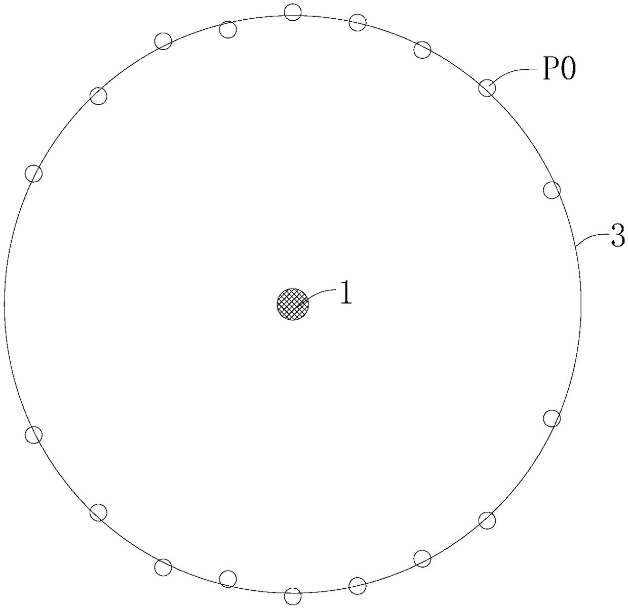
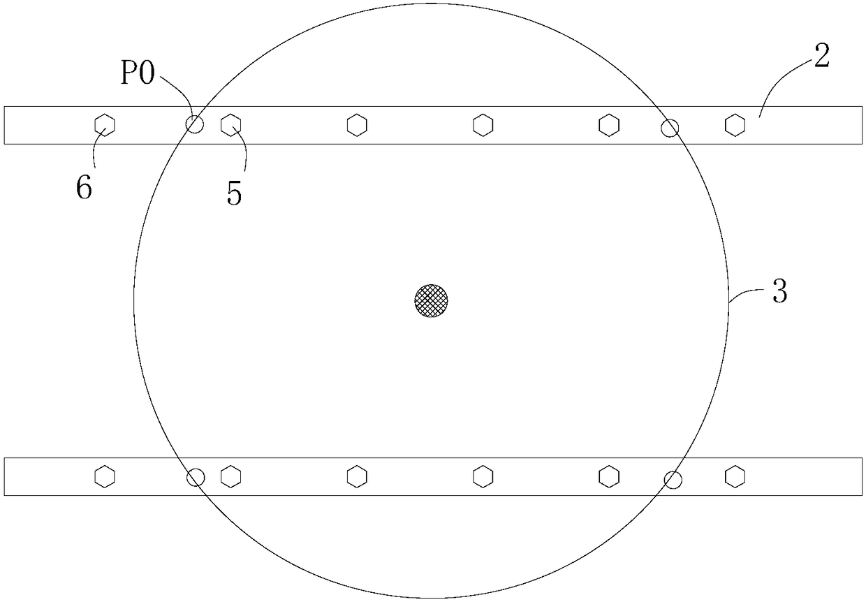
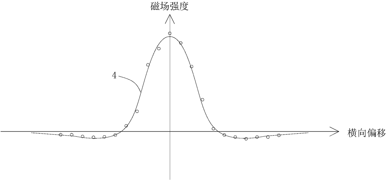
The invention belongs to the field of object positioning methods and particularly relates to a magnetic-nail positioning method. The magnetic-nail positioning method comprises the following steps of:(a) arranging at least two groups of magnetic sensors, placing the two groups of magnetic sensors above the area of the magnetic nail at a certain interval; (b) according to the two groups of magneticsensors, collecting measurement points P0 with same magnetic-field intensity; (c) according to all the collected measurement points P0, fitting out a magnetic-field intensity distribution curve of the points P0; (d) according to the distribution curve of the points P0, deducing a point Pmax with maximum magnetic-field intensity, and obtaining the position of the magnetic nail. The magnetic-nail positioning method is characterized in that enough measurement points P0 can be collected under a static condition, the distribution curve of the points P0 can be fit out by the measurement points P0 with the same magnetic-field intensity, the point Pmax with the maximum magnetic-field intensity can be deduced, and the position of the magnetic nail is below the point Pmax. Compared with the prior art, the magnetic-nail positioning method has the advantages of accurate positioning, low application-equipment cost and real-time feedback of positioning results.

Description

technical field [0001] The invention belongs to the field of object positioning methods, and specifically relates to a magnetic nail positioning method, a navigation error correction method using the method, and a magnetic field induction positioning device. Background technique [0002] As people have higher and higher requirements for the accuracy of AGV operation, in order to solve the problem that the magnetic nail positioning method used in general AGV is sensitive to sensor hardware errors, the positioning error is large, and it cannot be positioned in real time at any time. It is a method to use a sufficient amount of magnetic field data that can be measured in real time with small hardware errors to fit and calculate the position of the magnetic nail, so that the AGV can accurately correct the navigation error in real time. [0003] The key to this navigation error correction method using magnetic nail positioning is how to accurately determine the position of the ma...

Claims


Application Information

Patent Timeline
IPC IPC(8): G01C25/00
CPCG01C25/00
Inventor 霍伟祺
Owner GUANGDONG JATEN ROBOT & AUTOMATION
Why Eureka
Try Eureka