Power transferring apparatus and processing box

A technology of a power transmission device and a power transmission part, which is applied in the fields of electrography, optics, instruments, etc., can solve the problems of the power receiving part falling off, the power receiving part and the driving gear not being tightly fitted, etc.

Pending Publication Date: 2018-06-12
ZHUHAI TUOJIA TECH
View PDF0 Cites 2 Cited by
  • Summary
  • Abstract
  • Description
  • Claims
  • Application Information

AI Technical Summary

Problems solved by technology

[0005] However, just because of the existence of the spherical body, the power receiving part is not tightly fitted with the end of the driving gear, so the power receiving part may fall off from the process box during transportation of the process box adopting this power receiving part. risks of

Method used


Image

  • Power transferring apparatus and processing box
  • Power transferring apparatus and processing box
  • Power transferring apparatus and processing box

Examples


Embodiment Construction

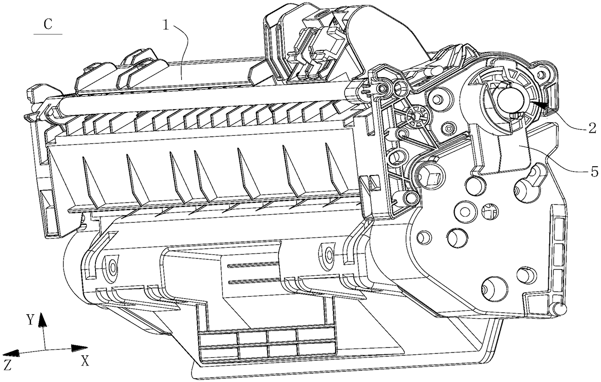
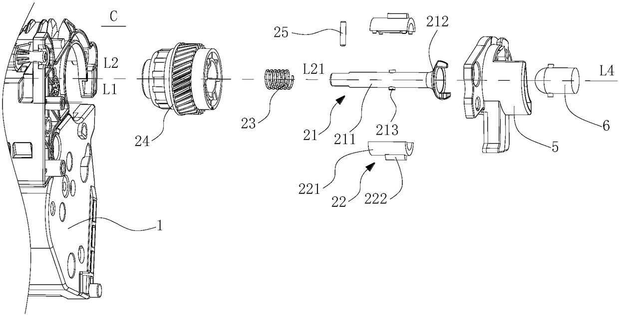
[0035] Embodiments of the present invention will be described in detail below in conjunction with the accompanying drawings. For the convenience of description, first define the process box as follows: define the length direction of the process box C as longitudinal X, the installation direction of process box C as horizontal Y, and the direction perpendicular to both the longitudinal X and horizontal Y of the process box is vertical Z.

[0036] figure 1 It is a schematic diagram of the overall structure of the process box involved in the present invention. The process cartridge C is detachably mounted in the image forming apparatus having the power output 6 .

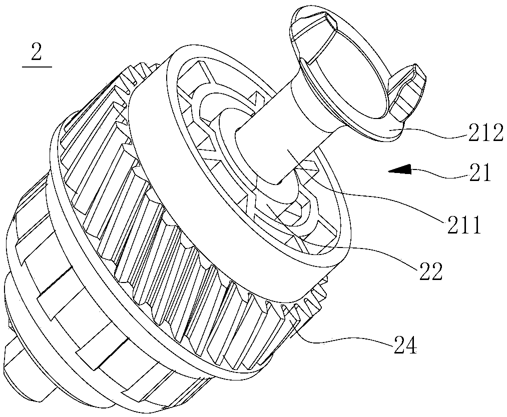
[0037] As shown in the figure, the process cartridge C includes a process cartridge housing 1, a power transmission device 2 detachably installed at one longitudinal end of the process cartridge housing 1, and the power transmission device 2 is used to communicate with a power output member 6 ( Such as figure 2 sh...


PUM


Abstract

The invention relates to a power transferring apparatus. The power transferring apparatus has a rotation axis L2 and comprises a power receiving part, a moving part and a driving gear; the moving partcomprises a body, a bump projecting from the outer surface of the body and a sliding groove extending towards the outer surface from the inner surface of the body, and the power receiving part is combined with the sliding groove; the driving gear comprises a cylindrical gear body, a gear cavity formed by encircling the gear body, and an accommodating groove extending in a direction away from therotation axis L2 from the side wall of the gear cavity; a step surface is formed between the accommodating groove and the gear cavity; and the power receiving part can be stretched and retracted in the direction of the rotation axis L2, when the power receiving part stretches, the bump is disposed on a first position, when the power receiving part is retracted, the bump is disposed on a second position closer to the step surface than the first position, the power receiving part is connected with the driving gear in the power transferring apparatus in a close fit manner rather than the connection of a ball-shaped body, so that in the transportation process of a processing box, the problem that the moving receiving part is separated from the processing box can be avoided.

Description

technical field [0001] The present invention relates to the field of electrophotographic imaging, in particular to a process box suitable for electrophotographic imaging equipment and a power transmission device located in the process box, the power transmission device is used for coupling and disengagement with a power output member in the imaging equipment, When the power transmission device is combined with the power output member, the power transmission device receives the driving force output from the power output member, and transmits the received driving force to components in the process cartridge. Background technique [0002] Common electrophotographic imaging equipment, such as printers, copiers, etc., are indispensable equipment in the modern office field. Taking a printer as an example, a process cartridge is a commonly used consumable in a printer, in which a developer for development is accommodated, and a plurality of rotating members are rotatably installed ...

Claims


Application Information

Patent Timeline
IPC IPC(8): G03G21/18
CPCG03G21/186
Inventor 周欣闻艺俊
Owner ZHUHAI TUOJIA TECH
Why Eureka
Try Eureka