A method and system for dimming LEDs based on ambient brightness

A technology of ambient brightness and LED driving, which is applied in the field of LED dimming method and system based on ambient brightness, can solve the problems of long photosensitive signal and dimming signal transmission lines, high cost of adding lines, and distortion of dimming signals, etc., to achieve dimming High light accuracy, avoiding electromagnetic compatibility problems, convenient and feasible dimming scheme

Active Publication Date: 2020-06-19
TRIDONIC
View PDF11 Cites 0 Cited by
  • Summary
  • Abstract
  • Description
  • Claims
  • Application Information

AI Technical Summary

Problems solved by technology

[0004] The disadvantage of this solution is that since the photosensitive device is usually installed together with the lighting fixture to sense the ambient brightness, and the light source driver is installed outside the lamp, the process of transmitting the ambient brightness signal and converting it into a dimming signal requires an additional dimming signal Transmission line and MCU processor
Especially in the field of outdoor lighting, when the distance between the light source driver and the LED lamps and photosensitive devices is relatively long, a long transmission line for the photosensitive signal and dimming signal is required. Distortion of dimming signal

Method used


Image

  • A method and system for dimming LEDs based on ambient brightness
  • A method and system for dimming LEDs based on ambient brightness
  • A method and system for dimming LEDs based on ambient brightness

Examples


Embodiment Construction

[0038] The present invention will be further described in detail below with reference to the accompanying drawings and in combination with specific embodiments.

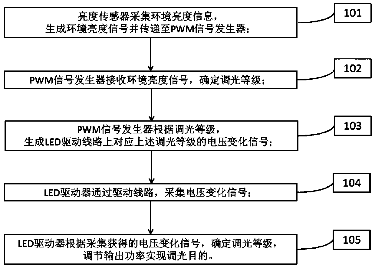
[0039] A kind of LED dimming method based on ambient brightness provided by the present invention, such as figure 1 shown, including the following steps:

[0040] Step 101, the brightness sensor collects ambient brightness information, generates an ambient brightness signal, and transmits the ambient brightness signal to a PWM signal generator;

[0041] Step 102, the PWM signal generator receives the ambient brightness signal, and determines the dimming level;

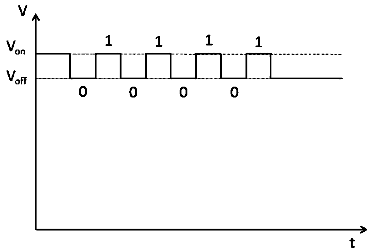
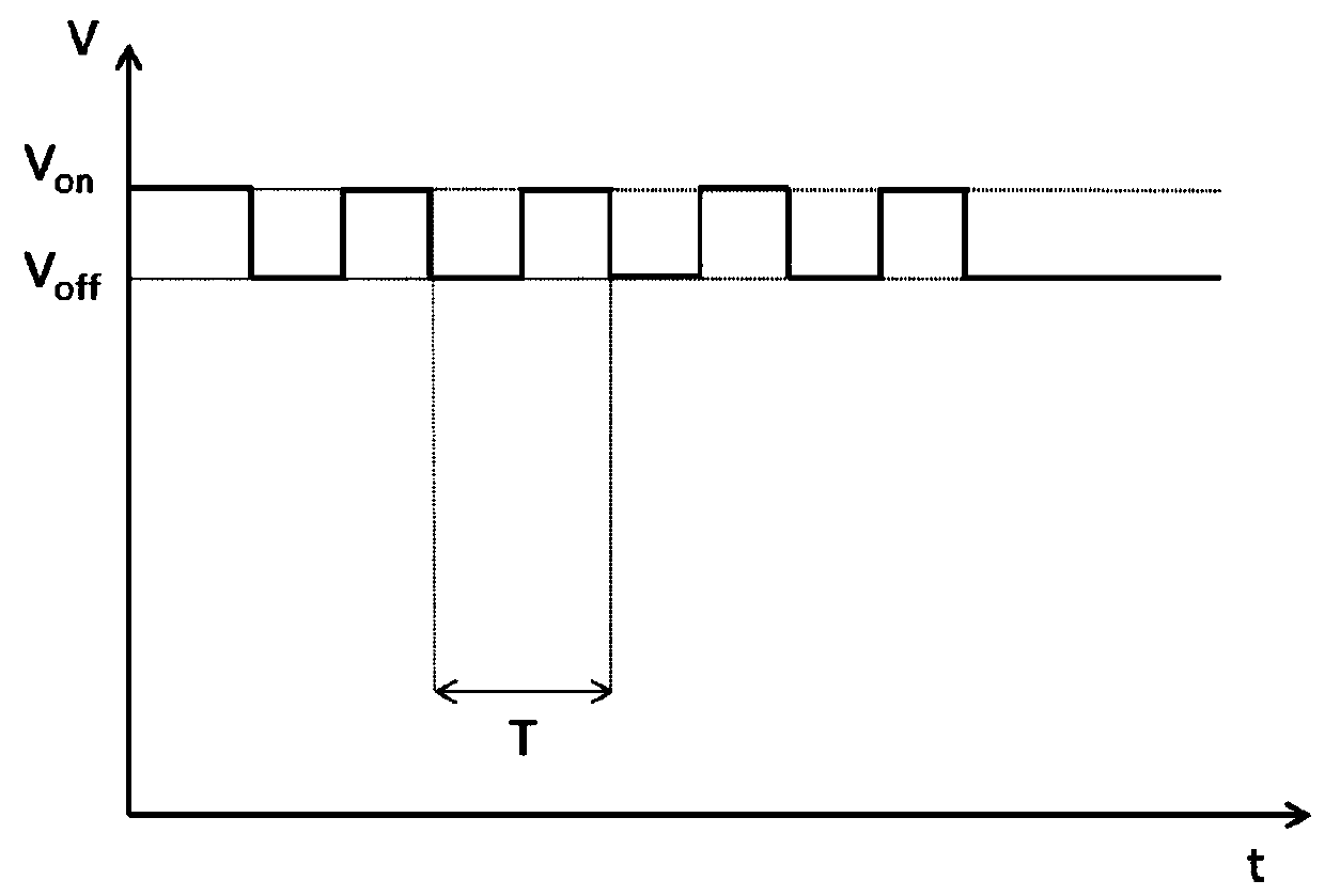
[0042] Step 103, the PWM signal generator generates a voltage change signal corresponding to the dimming level according to the dimming level;

[0043] Step 104, the LED driver collects the above-mentioned voltage change signal through the LED driving circuit;

[0044] Step 105, the LED driver determines the dimming level according to the collected voltage...


PUM


Abstract

The invention provides an LED dimming method and system based on ambient brightness, which collects ambient brightness information through a brightness sensor, generates an ambient brightness signal, and transmits the ambient brightness signal to a PWM signal generator; the PWM signal generator receives the ambient brightness signal, Determine the dimming level; the PWM signal generator generates a voltage change signal corresponding to the dimming level on the LED drive line according to the dimming level; the LED driver collects the voltage change signal through the drive line, and according to the collected voltage The change signal determines the dimming level, and the output power is adjusted to achieve the purpose of dimming. The invention transmits the dimming information through the voltage change signal on the LED driving circuit, and solves the problems of equipment cost, installation cost and electromagnetic compatibility caused by additionally adding a dimming signal transmission circuit in the prior art.

Description

technical field [0001] The invention relates to the technical field of LED driving, in particular to an LED dimming method and system based on ambient brightness. Background technique [0002] Due to the advantages of energy saving and environmental protection, LED has been widely used as a new generation of lighting source. The LED dimming device can enable the LED lighting system to sense the brightness of the external environment and perform dimming, saving energy while providing a more intelligent and comfortable lighting environment. [0003] In the existing LED lighting system dimming control scheme according to the ambient brightness, after the photosensitive device detects the ambient brightness, it transmits the ambient brightness signal to the MCU (Micro Controller Unit, Micro Control Unit) module, and the MCU module converts the ambient brightness signal into a dimming signal. The light signal and the dimming signal are sent to the LED driver, and the LED driver ...

Claims


Application Information

Patent Timeline
Patent Type & Authority Patents(China)
IPC IPC(8): H05B45/12H05B45/325H05B44/00
CPCH05B45/12
Inventor 钟国基毛秋翔
Owner TRIDONIC
Why Eureka
Try Eureka