Test tube cleaning machine

A technology for cleaning machines and test tubes, which is applied in the directions of cleaning hollow objects, cleaning methods and utensils, chemical instruments and methods, etc., and can solve the problems of inability to clean the test tubes, puncture, and the inability of the brush tube to extend into the test tube.

Inactive Publication Date: 2018-06-15
重庆骄直电气有限公司
View PDF8 Cites 9 Cited by
  • Summary
  • Abstract
  • Description
  • Claims
  • Application Information

AI Technical Summary

Problems solved by technology

But, when all test tubes will be in the state of being placed (that is, the state with the opening facing upwards), the brush tube can be stretched into the test tubes, and the test tube groove can be rotated to clean the test tubes. When one or more test tubes are placed upside down , the brush tube cannot extend into the test tube, and the test tube cannot be cleaned. If the force is too strong, the brush tube may even puncture the bottom of the inverted test tube

Method used


Image

  • Test tube cleaning machine

Examples


Embodiment Construction

[0014] The present invention will be further described in detail below through specific embodiments:

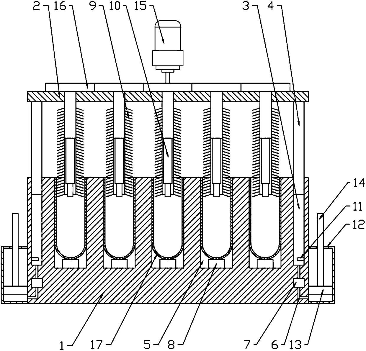
[0015] The reference signs in the drawings of the specification include: box body 1, cover plate 2, support hole 3, support column 4, receiving hole 5, drain hole 6, solenoid valve 7, electric switch 8, cleaning brush 9, telescopic rod 10 , Travel switch 11, recovery box 12, piston 13, push rod 14, motor 15, driven gear 16, test tube 17.

[0016] The embodiment of the test tube cleaning machine is basically as attached figure 1 Shown: It includes a power supply, a box body 1 and a cover plate 2 that covers the upper part of the box body 1. The four corners of the box body 1 are respectively provided with a supporting hole 3, and the box body 1 is also arrayed with 5×5 to be accommodated. The accommodating hole 5, the supporting hole 3 and the accommodating hole 5 of the cleaning test tube 17 are all vertically arranged blind holes. The supporting column 4 is slidably connected in...


PUM


Abstract

The invention relates to the field of container cleaning, and discloses a test tube cleaning machine comprising a power supply, a box body and a cover plate. The upper surface of the box body is provided with a plurality of supported holes and a plurality of receiving holes, and the supported holes and the receiving holes are all blind holes vertically formed; the interior of each supported hole is slidably connected to a support column, and the support columns and the supported holes are slidably sealed; the supported holes are internally filled with fluids, and the support columns are located above the fluids; the top ends of the support columns are connected to the cover plate; the central position of the bottom surface of each supported hole is provided with a normally ON electric switch which is smaller than the inner diameter of a test tube to be cleaned, and the bottom of each supported hole is provided with a drainage hole which is internally provided with a valve body which isopened after power-on; the valve body and the power supply are connected to all electric switches in series; a cleaning brush used for cleaning the test tube is arranged above each receiving hole, and rotatably connected to the cover plate; and the cover plate is provided with a driving device for driving the cleaning brush to rotate. The invention aims to provide equipment for cleaning the testtubes in batches after it is detected that the test tubes are placed rightly.

Description

Technical field [0001] The present invention relates to the field of container cleaning (B0809). Background technique [0002] A test tube is a kind of test aid often used in chemical tests. The test tube is a glass tube with an open top and a closed bottom. The length of the test tube ranges from several centimeters to 20 centimeters, and the diameter is between several millimeters to several centimeters. In the course of experiments, test tubes are often used for various chemical experiments. The test tube is an important tool in the entire testing process, and cleaning the used test tube is an important step in the post-processing of the experiment. The existing test tube cleaning method is to clean the test tubes one by one with a hand-held test tube brush. However, when a large number of test tubes need to be cleaned, manual cleaning is slow due to the large number, which will increase the working time of post-test processing, so there is an urgent need to increase the clea...

Claims


Application Information

Patent Timeline
IPC IPC(8): B08B9/087
Inventor 任廷军
Owner 重庆骄直电气有限公司
Why Eureka
Try Eureka