a positioning device
A positioning device and positioning pin technology, which is applied in the field of mechanical processing, can solve the problems of complex structure, high cost, and inaccurate positioning accuracy of the positioning device, and achieve the effects of low labor intensity, good stability, and fast clamping
- Summary
- Abstract
- Description
- Claims
- Application Information
AI Technical Summary
Problems solved by technology
Method used
Image
Examples
Embodiment 1
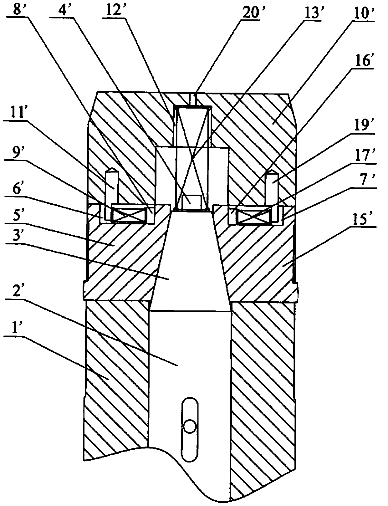
[0038] In this embodiment, in order to solve the problems of high production cost and complex structure of the hydraulic expansion shaft in the prior art, it also solves the problem that the mechanical elastic mandrel can only be used for small-diameter positioning, and the positioning problem in the prior art The problem of inaccurate positioning accuracy of the tensioning block exists in the tensioning mechanism.
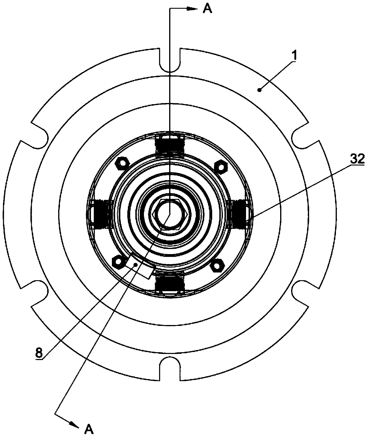
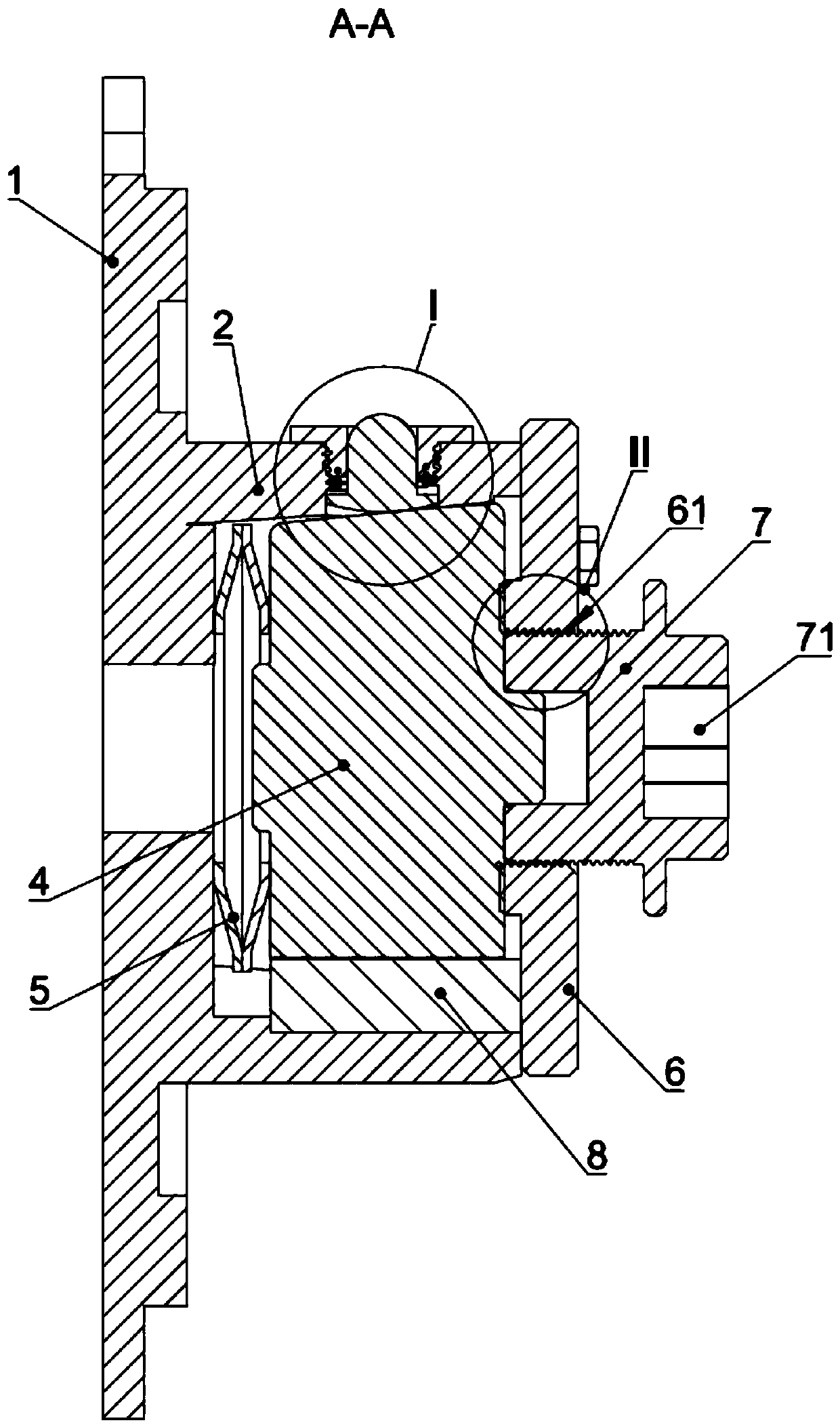
[0039] Such as Figure 2-4 As shown, this embodiment provides a positioning device, which includes a base 1 , a positioning structure 3 , a mandrel 4 , an end cover 6 , a tightening bolt 7 , a second elastic member 5 and a positioning member 8 . Wherein, the base 1 is provided with a trough-shaped piece 2, and the side wall of the trough-shaped piece 2 is provided with first holes 21 evenly distributed in the circumferential direction. Preferably, the above-mentioned trough-shaped piece 2 is circular, and the number of the first holes 21 is four , and uniformly a...
Embodiment 2
[0056] On the basis of the first embodiment above, the difference from the first embodiment above is:
[0057] In this embodiment, the grooved part 2 and the end cover 6 are integrally formed. After the mandrel 4, the tightening bolt 7, the grooved part 2 and the positioning structure 3 are installed, the second elastic part 5 is installed on the base 1 and the Between the mandrels 4, the base 1 is fixedly connected with the integrally formed part of the groove part 2 and the end cover 6, that is, the positioning device in this embodiment is formed.
Embodiment 3
[0059] On the basis of the first embodiment above, the difference from the first embodiment above is:
[0060] On the end cap 6 in this embodiment, a second hole is provided at the center of the end cap 6. The second hole in this embodiment is a through hole, which acts on the core through the through hole of the end cap 6 by means of an external structure. On the shaft 4 , the external structure provides power for the reciprocating movement of the mandrel 4 inside the channel member 2 . The above-mentioned external structure can drive the mandrel 4 to move through the protruding end of the air cylinder, or manually pass the tool through the above-mentioned through hole to push the mandrel 4 to reciprocate along the groove-shaped member 2, and at the same time use the above-mentioned tool to move the mandrel 4 in the groove. The position in the shape part 2 is fixed.
PUM
 Abstract
Description
Claims
Application Information
 - R&D
- Intellectual Property
- Life Sciences
- Materials
- Tech Scout
- Unparalleled Data Quality
- Higher Quality Content
- 60% Fewer Hallucinations
Browse by: Latest US Patents, China's latest patents, Technical Efficacy Thesaurus, Application Domain, Technology Topic, Popular Technical Reports.
© 2025 PatSnap. All rights reserved.Legal|Privacy policy|Modern Slavery Act Transparency Statement|Sitemap|About US| Contact US: help@patsnap.com


