Servo annular nozzle device

A technology of annular nozzles and nozzles, applied in grinding/polishing safety devices, metal processing equipment, grinding/polishing equipment, etc., can solve problems such as narrow cooling range, impact on grinding head life, waste of resources, etc., to improve product quality efficiency, reduce production costs, and ensure adequate cooling

Pending Publication Date: 2018-06-15
BEIJING JINGDIAO GRP CO LTD
View PDF5 Cites 1 Cited by
  • Summary
  • Abstract
  • Description
  • Claims
  • Application Information

AI Technical Summary

Problems solved by technology

[0002] At present, there are two main cooling methods for grinding heads in mechanical processing: one is to use single or multiple nozzles to cool specific processing points. This method has narrow cooling range, easy to produce circumferential gaps, and uneven cooling. And other defects, resulting in insufficient processing cooling, high product rejection rate, and also have a great impact on the life of the grinding head; another cooling method is to use annular water curtain for cooling, which requires a large water flow , for the centralized water delivery of multiple machine tools, the circulating water consumption is too large, which is likely to cause waste of resources. At the same time, the requirements for the waterproof level of the machine tool shield are also high, which is easy to increase the production cost of the machine tool

Method used


Image

  • Servo annular nozzle device
  • Servo annular nozzle device
  • Servo annular nozzle device

Examples


Embodiment Construction

[0013] The present invention will be further described in detail below in conjunction with the drawings and specific embodiments.

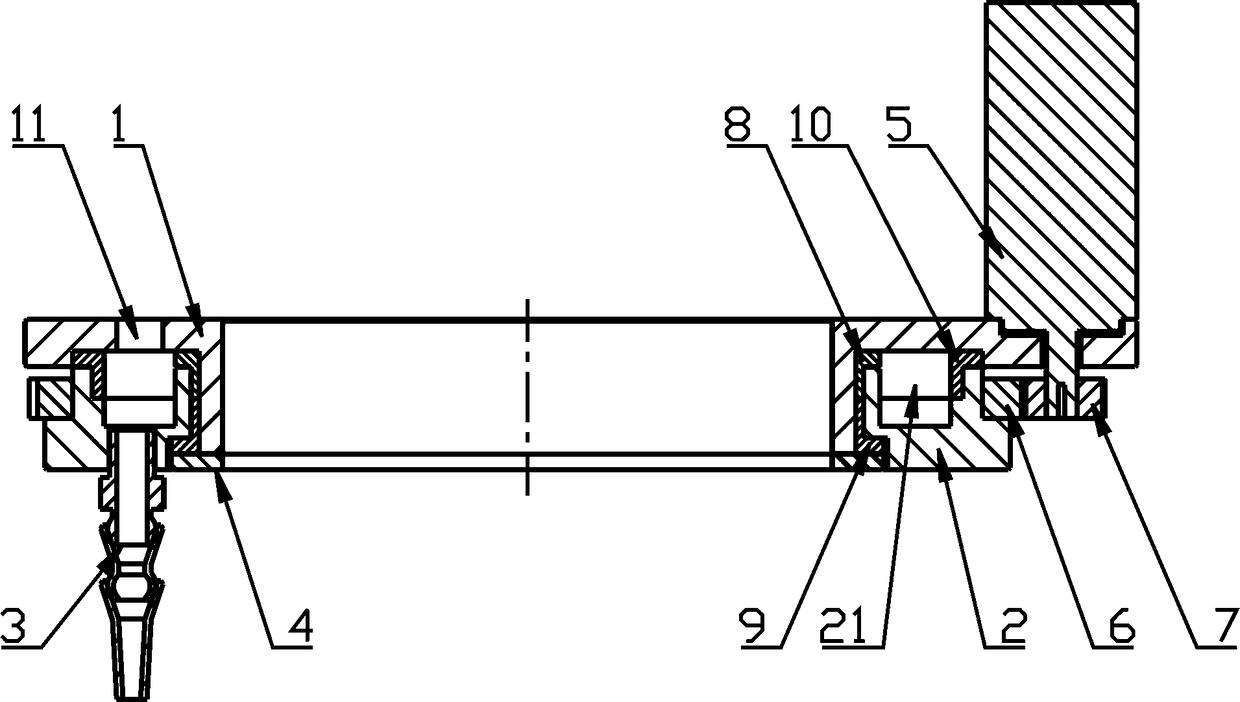
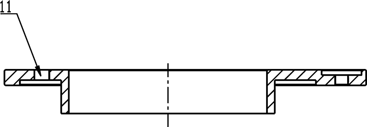
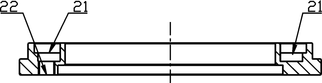
[0014] Combine Figure 1 to Figure 3 As shown, a servo annular nozzle device of the present invention is composed of a fixed inner ring 1, a rotating outer ring 2, a nozzle 3, a lower support plate 4, a servo motor 5, a large gear 6 and a small gear 7.

[0015] The fixed inner ring 1 is an outer flange structure, and the top end is provided with an outwardly extending top flange; the rotating outer ring 2 is sleeved on the fixed inner ring 1, and is axially positioned by the lower support plate 4; the lower support plate 4 is fixedly installed At the bottom of the fixed inner ring 1. The rotating outer ring 2 is provided with an annular chamber 21 with a U-shaped cross section, and forms a closed flow channel with the top flange of the fixed inner ring 1; the bottom of the annular chamber 21 is provided with a water outlet 22, and the nozzle 3 is inst...


PUM


Abstract

The invention belongs to the technical field of mechanical machining, and particularly relates to a servo annular nozzle device. The servo annular nozzle device is composed of a fixed inner ring, a rotary outer ring, a nozzle, a lower supporting plate, a servo motor and a transmission device. The rotary outer ring is arranged on the fixed inner ring in a sleeved manner and is supported and positioned through the lower supporting plate installed at the bottom of the fixed inner ring. The rotary outer ring is provided with an annular cavity and forms a sealed flow channel with the fixed inner ring. The bottom of the annular cavity is provided with a water outlet, and the nozzle is installed on the water outlet. The fixed inner ring is provided with a water inlet corresponding to the annularcavity. The rotary outer ring is connected with the servo motor through the transmission device and can rotate around the center axis of the servo motor under the action of the servo motor; and the servo motor is installed on the fixed inner ring. The servo annular nozzle device is simple in structure, real-time tracking cooling of machined points can be achieved, and the cooling effect is fully guaranteed.

Description

Technical field [0001] The invention belongs to the technical field of mechanical processing, and particularly relates to a servo ring nozzle device. Background technique [0002] At present, there are two main cooling methods for grinding heads in machining: one is to use single or multiple nozzles to cool specific processing points. This method has narrow cooling range, easy to produce circumferential gaps, and uneven cooling. And other defects, resulting in insufficient processing and cooling, high product rejection rate, and a great impact on the life of the grinding head; another cooling method is to use an annular water curtain for cooling, which requires a large water flow For the centralized water delivery of multiple machine tools, the circulating water consumption is too large, which is easy to cause waste of resources. At the same time, the waterproof level of the machine tool guard is also high, which is easy to increase the production cost of the machine tool. Summa...

Claims


Application Information

Patent Timeline
Patent Type & Authority Applications(China)
IPC IPC(8): B24B55/02
CPCB24B55/02
Inventor 贾军政栗瑞庆
Owner BEIJING JINGDIAO GRP CO LTD
Why Eureka
Try Eureka