
Water supply throttling system based on temperature control and control method

A temperature control and controller technology, used in hydropower generation, safety devices, machines/engines, etc., it can solve the problems of wasting cooling water, increasing valve opening, and maintaining the same, so as to ensure safe operation and safety. and reliability, assuring security and stability

Active Publication Date: 2022-05-27
CHINA YANGTZE POWER
View PDF6 Cites 0 Cited by
  • Summary
  • Abstract
  • Description
  • Claims
  • Application Information

AI Technical Summary

Problems solved by technology

[0002] The technical water supply system currently used in a power station mainly provides cooling water for the upward guide cooler, generator air cooler, derivation cooler, and water guide cooler. During the water supply process, the flow adjustment method is mainly to manually adjust the opening of the ball valve. After the valve is adjusted, the valve state will remain unchanged. When the temperature of the cooler changes, the flow into the cooler cannot be changed. At the same time, in order to ensure that the cooler has enough cooling water to cool, the opening of the valve is often increased. , excess cooling water will be wasted

Method used


Image

  • Water supply throttling system based on temperature control and control method
  • Water supply throttling system based on temperature control and control method
  • Water supply throttling system based on temperature control and control method

Examples


Embodiment 1

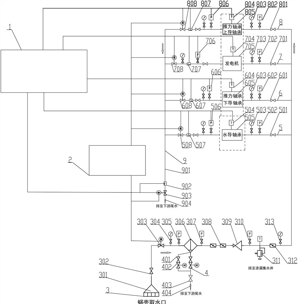
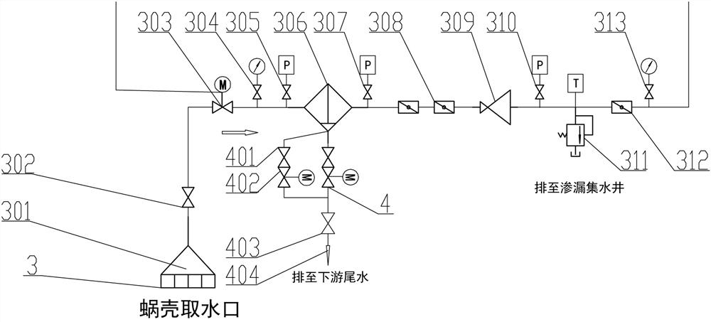
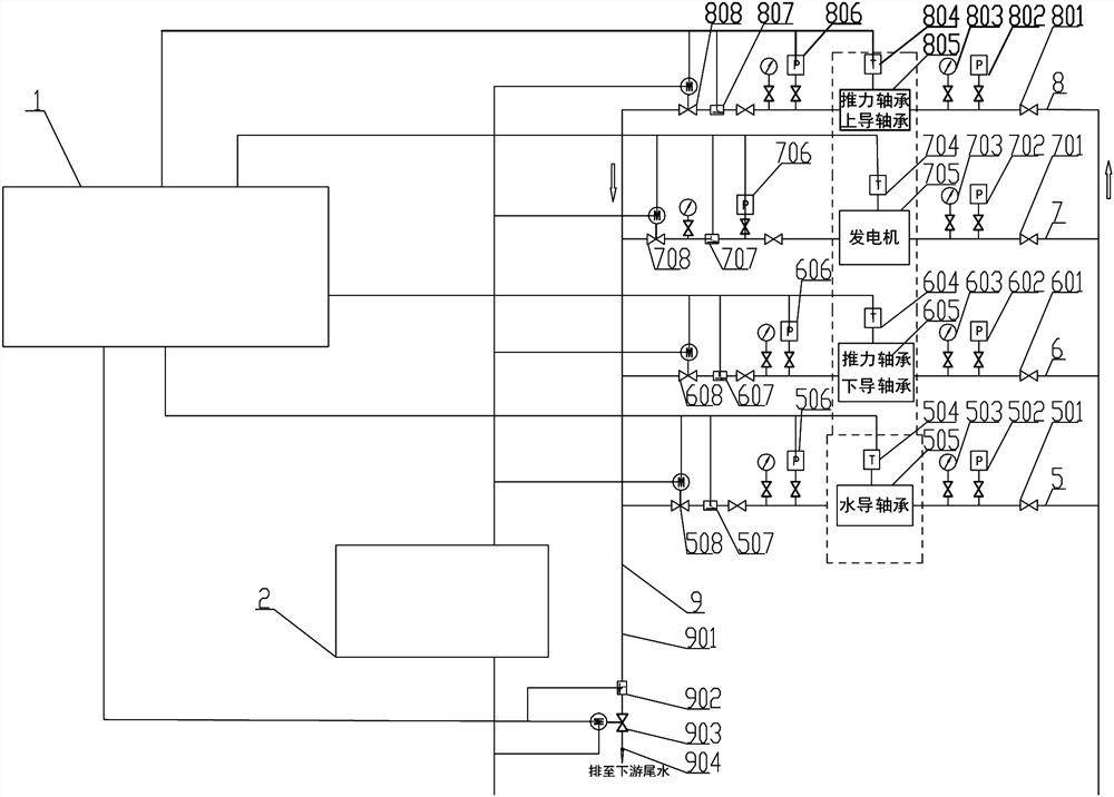
[0043] see Figure 1-3 , a water supply throttling system based on temperature control, which includes a water intake system 3 for introducing cooling water; an overflow system 4 for overflow is connected to the water intake system 3; The water guide bearing cooling system 5 for cooling the guide bearing, the thrust bearing lower guide bearing cooling system 6 for cooling the thrust bearing lower guide bearing, the generator air cooling system 7 for cooling the generator, and the thrust bearing cooling system 7 for cooling the thrust bearing. The upper guide bearing cooling system 8 of the thrust bearing cooling the upper guide bearing of the bearing; the cooling system 5 of the water guide bearing, the cooling system 6 of the lower guide bearing of the thrust bearing, the air cooling system 7 of the generator and the cooling system 8 of the upper guide bearing of the thrust bearing are all related to the signal acquisition. The signal collector 1 is used to collect the temper...

Embodiment 2

[0053] The control method of the water supply throttling system based on temperature control includes the following steps:

[0054] Step 1: During the operation of the system, the cooling water inside the volute is filtered and decompressed through the water intake system 3 and then introduced into the corresponding water guide bearing cooling system 5, thrust bearing lower guide bearing cooling system 6, and generator air cooling system 7 And thrust bearing upper guide bearing cooling system 8;

[0055] Step 2: During the operation of the water guide bearing cooling system 5, the temperature of the water guide bearing cooler 505 is collected in real time through the first temperature sensor 504, and the temperature signal is transmitted to the signal collector 1; The pipeline pressure is collected, and the pressure signal is transmitted to the signal collector 1; the pipeline flow is collected in real time through the first flow meter 507, and the flow signal is transmitted t...


PUM


Abstract

The invention provides a water supply throttling system based on temperature control and a control method. An overflow system used for overflowing is connected to a water taking system; the output end of the water taking system is connected with a water guide bearing cooling system used for cooling a water guide bearing and a thrust bearing lower guide bearing cooling system used for cooling a thrust bearing lower guide bearing in parallel. The generator air cooling system is used for cooling the generator; the thrust bearing upper guide bearing cooling system is used for cooling the thrust bearing upper guide bearing; the water guide bearing cooling system, the thrust bearing lower guide bearing cooling system, the generator air cooling system and the thrust bearing upper guide bearing cooling system are all connected with the signal collector; and the signal collector is connected with the valve opening controller. According to the system, the temperature change of the cooler can be monitored in real time, a corresponding coping method is made, the temperature of the cooler can be accurately guaranteed, and stable operation of a unit is achieved.

Description

technical field [0001] The invention relates to the technical field of water supply in power stations, and mainly relates to a water supply throttling system and a control method based on temperature control. Background technique [0002] The technical water supply system currently used in a power station mainly provides cooling water for the upper guide cooler, generator air cooler, derivation cooler and water guide cooler. During the water supply process, the flow adjustment method is mainly to manually adjust the opening of the ball valve. After the valve is adjusted, the valve state will remain unchanged. When the temperature of the cooler changes, the flow into the cooler cannot be changed. At the same time, in order to ensure that the cooler has enough cooling water for cooling, the opening of the valve is often increased. , the excess cooling water will be wasted. SUMMARY OF THE INVENTION [0003] The purpose of the present invention is to provide a water supply th...

Claims


Application Information

Patent Timeline
Patent Type & Authority Applications(China)
IPC IPC(8): F03B11/00F03B15/02
CPCF03B11/002F03B11/004F03B15/02Y02E10/20
Inventor 陈正新李帅访刘天雄
Owner CHINA YANGTZE POWER
Learn More