Plug-in type buffer valve

A buffer valve, cartridge technology, applied in the direction of lift valve, valve details, valve device, etc., can solve the problems of small flow capacity, high processing and assembly requirements, severe heat generation, etc., to meet the working conditions of large flow , The effect of effectively buffering the impact pressure, convenient processing and assembly

Inactive Publication Date: 2018-06-15
邵立坤
View PDF12 Cites 4 Cited by
  • Summary
  • Abstract
  • Description
  • Claims
  • Application Information

AI Technical Summary

Problems solved by technology

[0003] 1) It is a direct-acting relief valve with small flow capacity and severe heat generation, so it is not suitable for large-flow rotary devices
[0004] 2) It adjusts the screw sleeve to set the first-stage pressure, the pressure of the second oil port first rises rapidly to the first-stage pressure overflow, and at the same time, the buffer piston compresses the spring to raise the pressure of the second port to The second stage of pressure, although the rotary device can be started slowly by switching between the first stage of pressure and the second stage of pressure, but its structure is more complicated, the processing and assembly requirements are very high, and the failure rate is high

Method used


Image

  • Plug-in type buffer valve
  • Plug-in type buffer valve

Examples


Embodiment Construction

[0022] In order to make the technical solutions and advantages of the present invention clearer, the exemplary embodiments of the present invention will be further described in detail below in conjunction with the accompanying drawings. Apparently, the described embodiments are only a part of the embodiments of the present invention, and are not exhaustive of all the embodiments. And in the case of no conflict, the embodiments and the features in the embodiments of the present invention can be combined with each other.

[0023] The inventor noticed during the invention process that the existing direct-acting buffer overflow valve has a small flow capacity and is not suitable for a rotary device with a large flow rate. In addition, the existing buffer valve has a complex structure, high processing and assembly requirements, and a relatively high failure rate.

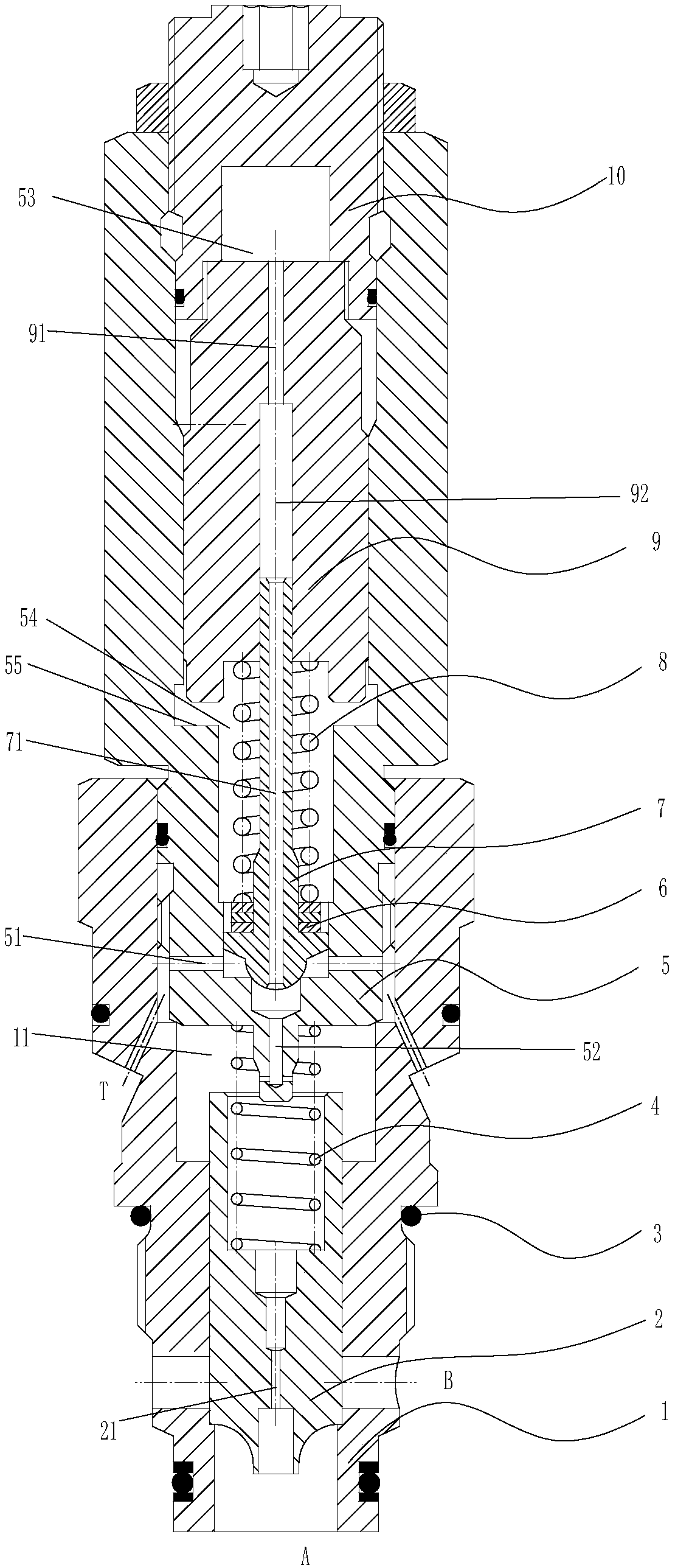
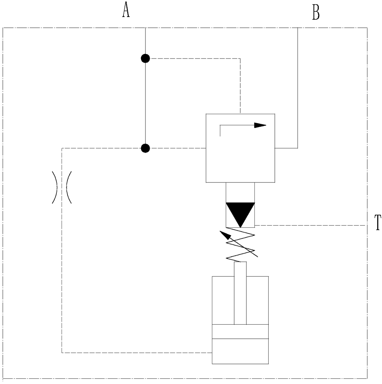
[0024] In view of the above disadvantages, an embodiment of the present invention proposes a plug-in buffer valve, wh...


PUM


Abstract

The invention provides a plug-in type buffer valve, which comprises a valve body, a main valve element, a thread sleeve, and a buffer piston, a pilot valve element and a second elastic element built in the thread sleeve. An oil port A, an oil port B and an oil port T are formed in the valve body; the oil port A is formed in one end of the valve body; the oil port B is formed in one end side face close to the oil port A; the oil port T is formed in the other end side face far away from the oil port A; the main valve element is movably arranged in the valve body and seals the oil port B; and a first damping channel leading to a control cavity from the oil port A is arranged on the main valve element. The plug-in type buffer valve meets a high-flow use condition, can be beneficial to effectively buffering impact pressure, and is simple in structure and low in cost.

Description

technical field [0001] The invention relates to the technical field of valves, in particular to a plug-in buffer valve. Background technique [0002] In modern mechanical equipment slewing devices, a large number of buffer function hydraulic circuits are used, such as excavator slewing devices, crane slewing devices, aerial work vehicle slewing devices, manipulator slewing devices and agricultural and forestry machinery slewing devices. In the above-mentioned rotary buffer circuit, the buffer valve is the key hydraulic component of this type of system, and the performance of the buffer valve directly affects the performance of the main engine. The existing buffer valves are divided into plate type buffer valves and cartridge type buffer valves according to the connection mode. In order to reduce the installation space and improve the system reliability in the system, the cartridge type buffer valves are generally used. For example, the authorized announcement number is CN20...

Claims


Application Information

Patent Timeline
Patent Type & Authority Applications(China)
IPC IPC(8): F15B13/02F16K1/32F16K1/36F16K31/122F16K31/36
CPCF15B13/021F16K1/32F16K1/36F16K31/1221F16K31/1226F16K31/36
Inventor 邵立坤
Owner 邵立坤
Why Eureka
Try Eureka