Nitrogen-containing waste liquid combustion furnace and its denitrification method

A combustion furnace and waste liquid technology, applied in the direction of combustion method, combustion type, incinerator, etc., can solve problems such as difficulty, cost increase, and material increase, and achieve the goal of preventing outflow from the furnace, preventing incomplete denitrification, and efficient incineration treatment Effect

Active Publication Date: 2020-04-21
NIPPON STEEL & SUMIKIN ENG CO LTD +1
View PDF2 Cites 0 Cited by
  • Summary
  • Abstract
  • Description
  • Claims
  • Application Information

AI Technical Summary

Problems solved by technology

However, in the vertical nitrogen-containing waste liquid combustion furnace, it is difficult to form a partition wall extending in the horizontal direction with bricks, or in order to make the partition board have a margin of strength, the cost may increase due to an increase in materials

Method used


Image

  • Nitrogen-containing waste liquid combustion furnace and its denitrification method
  • Nitrogen-containing waste liquid combustion furnace and its denitrification method
  • Nitrogen-containing waste liquid combustion furnace and its denitrification method

Examples


no. 1 Embodiment approach 〕

[0051] Hereinafter, a first embodiment of the present invention will be described based on the drawings.

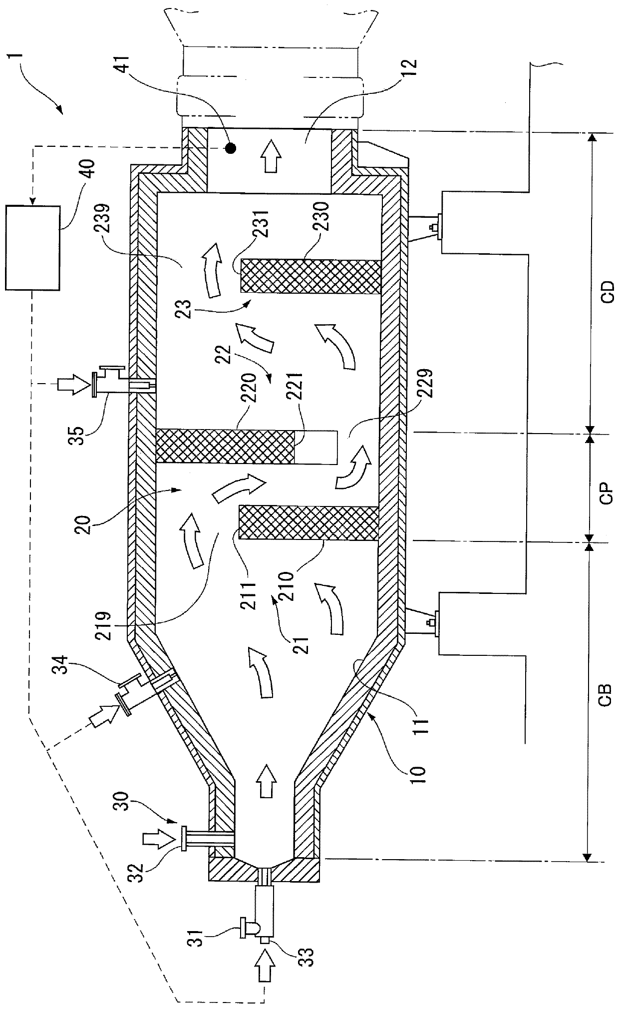
[0052] figure 1 Among them, the nitrogen-containing waste liquid combustion furnace 1 is a combustion furnace for incinerating nitrogen-containing waste liquid, and has a horizontal cylindrical furnace body 10 extending horizontally.

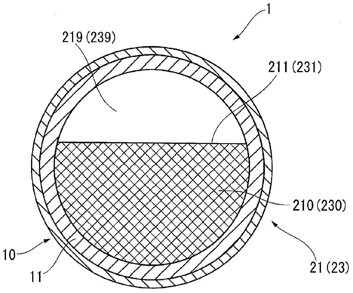
[0053] The shell of the furnace body 10 is formed by iron sheets, and bricks 11 are pasted on the inside as refractory materials. In the middle portion (area CP) of the furnace body 10, a partition structure 20 is provided.

[0054] The interior of the furnace body 10 is partitioned into the upstream side ( figure 1 Left side) of combustion chamber CB and downstream side ( figure 1 Right) Denitration chamber CD.

[0055] The upstream side end of the combustion chamber CB of the furnace body 10 is narrowed into a conical shape, and a burner 30 for combustion is provided at the front end. The burner 30 includes a fuel nozzle 31 , an air ...

no. 2 Embodiment approach 〕

[0106] Next, a second embodiment of the present invention will be described based on the drawings.

[0107] This embodiment is different from the above-mentioned first embodiment in the partition structure 20, but is common to the furnace body 10, the burner 30, and the control device 40. Therefore, description of these common configurations will be omitted, and the partition structure 20A of this embodiment will be described below.

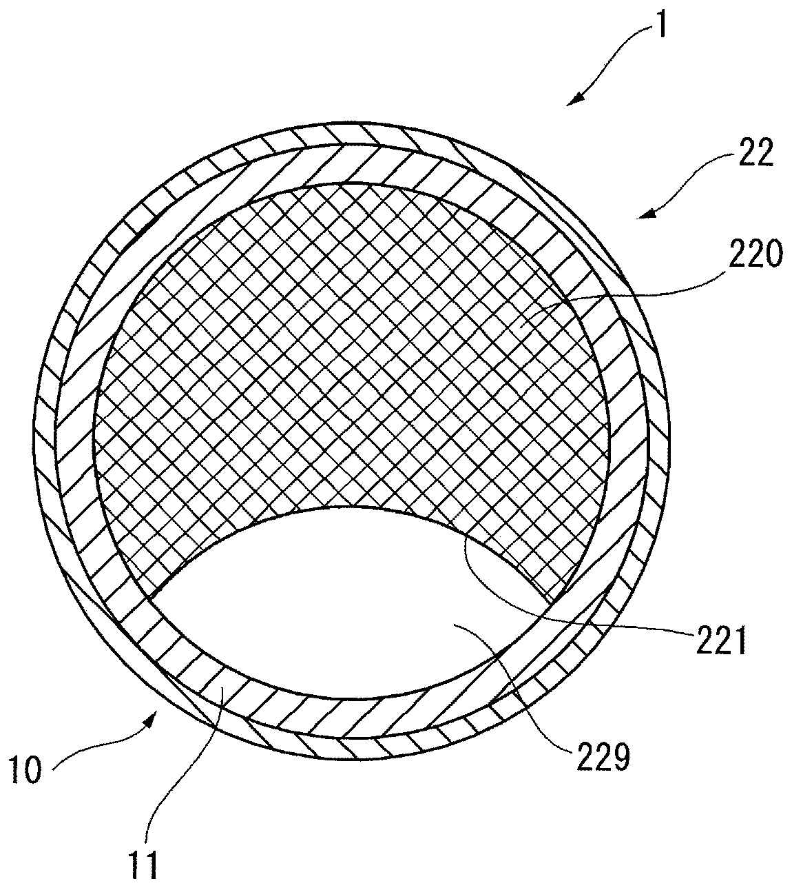
[0108] Figure 5 The horizontal cross-sectional shape of the furnace body 10 of this embodiment is shown in .

[0109] The furnace body 10 has bricks 11 attached to its substantially cylindrical inner surface, and is partitioned into a combustion chamber CB on the upstream side and a denitration chamber CD on the downstream side by a partition structure 20A provided in the region CP.

[0110] In the furnace body 10 , as in the above-mentioned first embodiment, a high-temperature gas is generated by the burner 30 in the combustion chamber CB, an...


PUM


Abstract

The utility model relates to a nitrogenous waste liquid burning furnace and a denitration method. The nitrogenous waste liquid burning furnace is provided with a horizontal type furnace body (10), ofwhich the inner surface made of bricks (11) and the extending direction is horizontal, and a separation structure (20) which divides the interior of the furnace body (10) into a combustion chamber (CB) on the upstream side and a denitration chamber (Cd) at the downstream side, wherein the separation structure (20) comprises a plurality of baffles (21, 22 ) which are arranged along the extending direction and having opening parts (219,229) formed in the part of the edges, and the opening parts (219,229) of adjacent baffles (21, 22 ) are formed on the opposite sides.

Description

technical field [0001] The invention relates to a nitrogen-containing waste liquid combustion furnace and a denitrification method thereof. Background technique [0002] Conventionally, incineration treatment of nitrogen-containing waste liquid has been performed. Nitrogen oxides are produced in the incineration treatment of nitrogenous waste liquid. In contrast, an ammonium source compound is added at a later stage of the incineration treatment to reduce nitrogen oxides generated by the denitration reaction. [0003] In Document 1 (Japanese Unexamined Patent Publication No. 8-233245), the furnace area of ​​the nitrogen-containing waste liquid combustion furnace is divided into a primary chamber on the upstream side and a secondary chamber on the downstream side, and additional air is injected into the secondary chamber. . Furthermore, the process of blowing ammonia into the secondary chamber was also performed. [0004] In Document 2 (Japanese Patent Application Laid-Op...

Claims


Application Information

Patent Timeline
Patent Type & Authority Patents(China)
IPC IPC(8): F23G7/04F23G5/50
CPCF23G5/50F23G7/04F23G2207/20
Inventor 辻孝典矶部悦四郎白石侑大菊地孝广
Owner NIPPON STEEL & SUMIKIN ENG CO LTD
Why Eureka
Try Eureka