Power line communication environment test device and method

A technology for power line communication and environmental testing, which is applied in the direction of measuring devices, measuring electricity, measuring electrical variables, etc., can solve problems such as difficult to solve on-site communication failures, and achieve the effect of improving the efficiency of fault handling and solving communication failures.

Inactive Publication Date: 2018-06-15
囯网河北省电力有限公司电力科学研究院 +2
View PDF4 Cites 6 Cited by
  • Summary
  • Abstract
  • Description
  • Claims
  • Application Information

AI Technical Summary

Problems solved by technology

[0004] The purpose of the present invention is to provide a power line communication environment test device and test met

Method used


Image

  • Power line communication environment test device and method
  • Power line communication environment test device and method
  • Power line communication environment test device and method

Examples


Embodiment 1

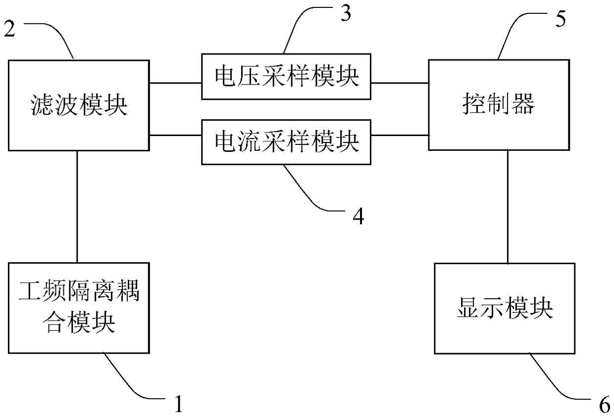
[0050] Embodiment 1 of the present invention provides a power line communication environment testing device. figure 1 It is a structural block diagram of the power line communication environment testing device provided by Embodiment 1 of the present invention. Such as figure 1 As shown, the power line communication environment testing device in this embodiment may include: a power frequency isolation coupling module 1, a filtering module 2, a voltage sampling module 3, a current sampling module 4, a controller 5 and a display module 6;

[0051] The power frequency isolation coupling module 1 is connected to the power line for receiving and isolating signals transmitted on the power line;

[0052] The filter module 2 is connected to the power frequency isolation coupling module 1 for filtering the isolated signal;

[0053] Both the voltage sampling module 3 and the current sampling module 4 are connected to the filtering module 2 for voltage sampling and current sampling;

...

Embodiment 2

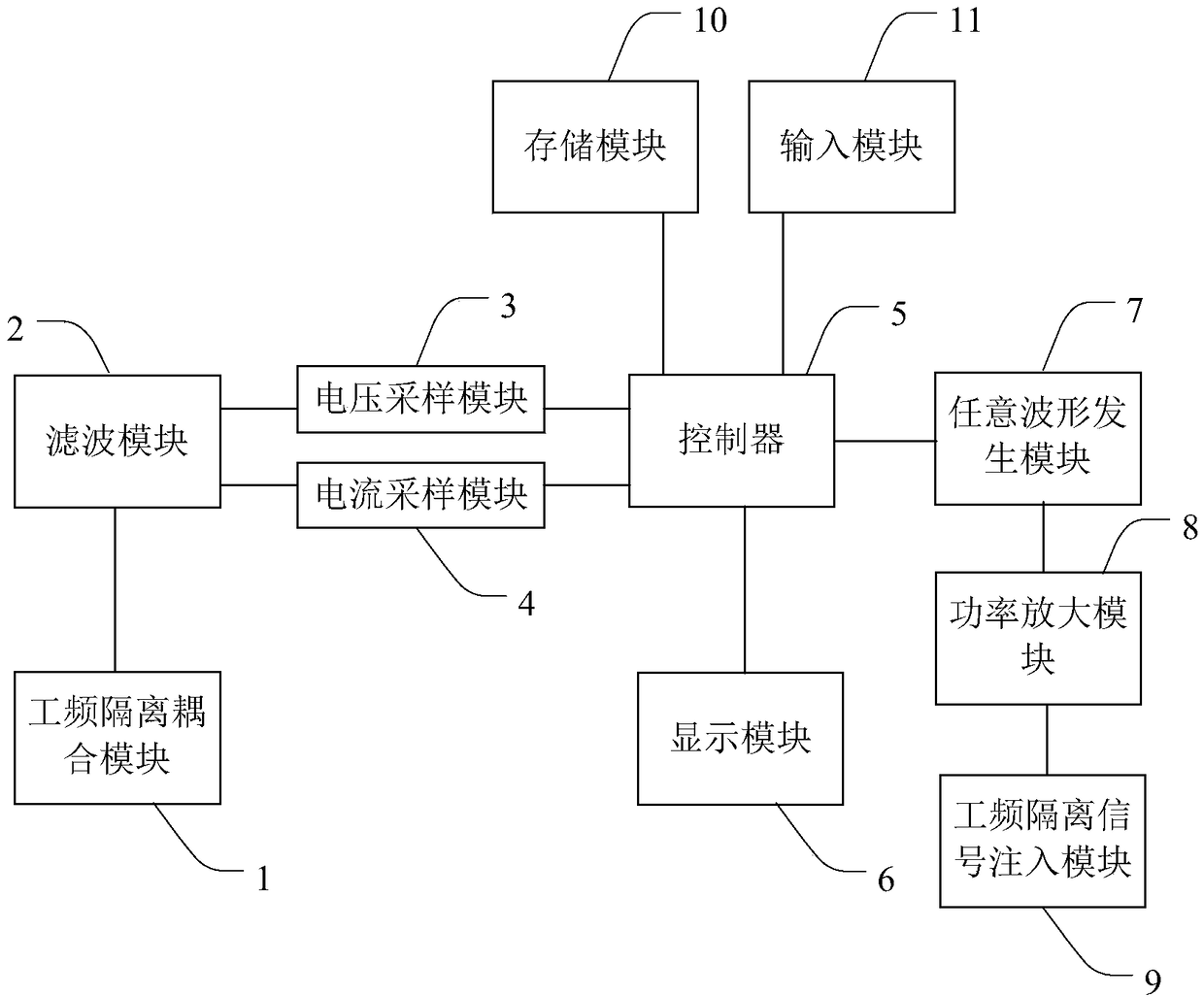
[0076] Embodiment 2 of the present invention provides a power line communication environment testing device. In this embodiment, on the basis of the technical solution provided in Embodiment 1, modules such as an arbitrary waveform generation module 7 , a power frequency isolation signal injection module 9 , and a power amplification module 8 are added to inject electrical signals into the power line.

[0077] figure 2 It is a structural block diagram of the power line communication environment testing device provided by the second embodiment of the present invention. Such as figure 2 As shown, the power line communication environment test device in this embodiment may include: a power frequency isolation coupling module 1, a filter module 2, a voltage sampling module 3, a current sampling module 4, a controller 5, a display module 6, and an arbitrary waveform generation module 7. Power amplification module 8 , power frequency isolation signal injection module 9 , storage ...

Embodiment 3

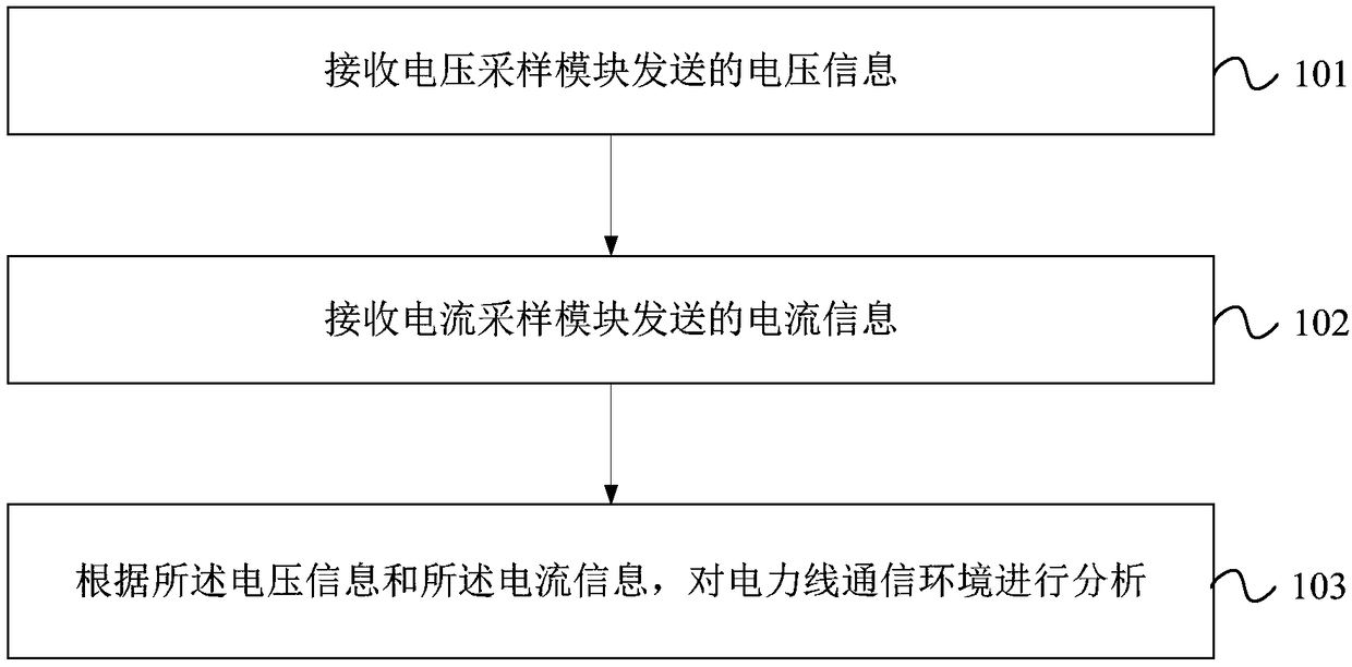
[0109] Embodiment 3 of the present invention provides a testing method based on the power line communication environment testing device described in any one of the above embodiments. image 3 It is a flow chart of the test method provided by Embodiment 3 of the present invention. Such as image 3 As shown, the method in this embodiment may include:

[0110] Step 101, receiving voltage information sent by the voltage sampling module.

[0111] Step 102, receiving the current information sent by the current sampling module.

[0112] Step 103, analyze the power line communication environment according to the voltage information and the current information.

[0113] The execution subject of the method in this embodiment may be a controller, and the specific principle and implementation method of the method may refer to any of the foregoing embodiments, which will not be repeated here.

[0114] The test method provided in this embodiment, receives the voltage information sent by...


PUM


Abstract

The present invention provides a power line communication environment test device and method. The device comprises a power frequency isolation coupling module, a filtering amplification filtering module, a voltage sampling module, a current sampling module, a controller and a display module. The power frequency isolation coupling module is connected with a power line, the filtering module is connected with the power frequency isolation coupling module, the voltage sampling module and the current sampling module are connected with the filtering module to perform voltage sampling and current sampling, the controller is configured to receive collected voltage information and current information and analyze a power line communication environment according to the voltage information and the current information, and the display module is connected with the controller and is configured to display an analysis result of the power line communication environment to users to allow the users to timely understand the problems of the power line communication environment so that communication faults are effectively solved and the fault processing efficiency is improved.

Description

technical field [0001] The invention belongs to the technical field of power control, and more specifically relates to a power line communication environment testing device and testing method. Background technique [0002] At present, one of the main ways of downlink communication in the power consumption information collection system is low-voltage power line carrier communication. Since the power carrier signal uses an open power line output, it is easily affected by the line environment and power load during transmission, causing carrier Communication is abnormal. [0003] After a communication failure occurs to a terminal device during on-site operation, due to the limited professional skills of the on-site maintenance personnel and the lack of professional maintenance tools, it is usually difficult to determine the cause of the failure on site, and it needs to be dismantled and sent for repair, which is time-consuming, laborious, and inefficient. The faults in the fiel...

Claims


Application Information

Patent Timeline
IPC IPC(8): G01R31/00
CPCG01R31/00
Inventor 李飞杨鹏申洪涛李翀王鸿玺石振刚
Owner 囯网河北省电力有限公司电力科学研究院
Why Eureka
Try Eureka